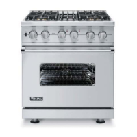
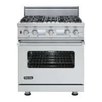
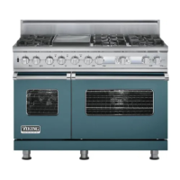
Troubleshooting
26 ©2009 Viking Preferred Service
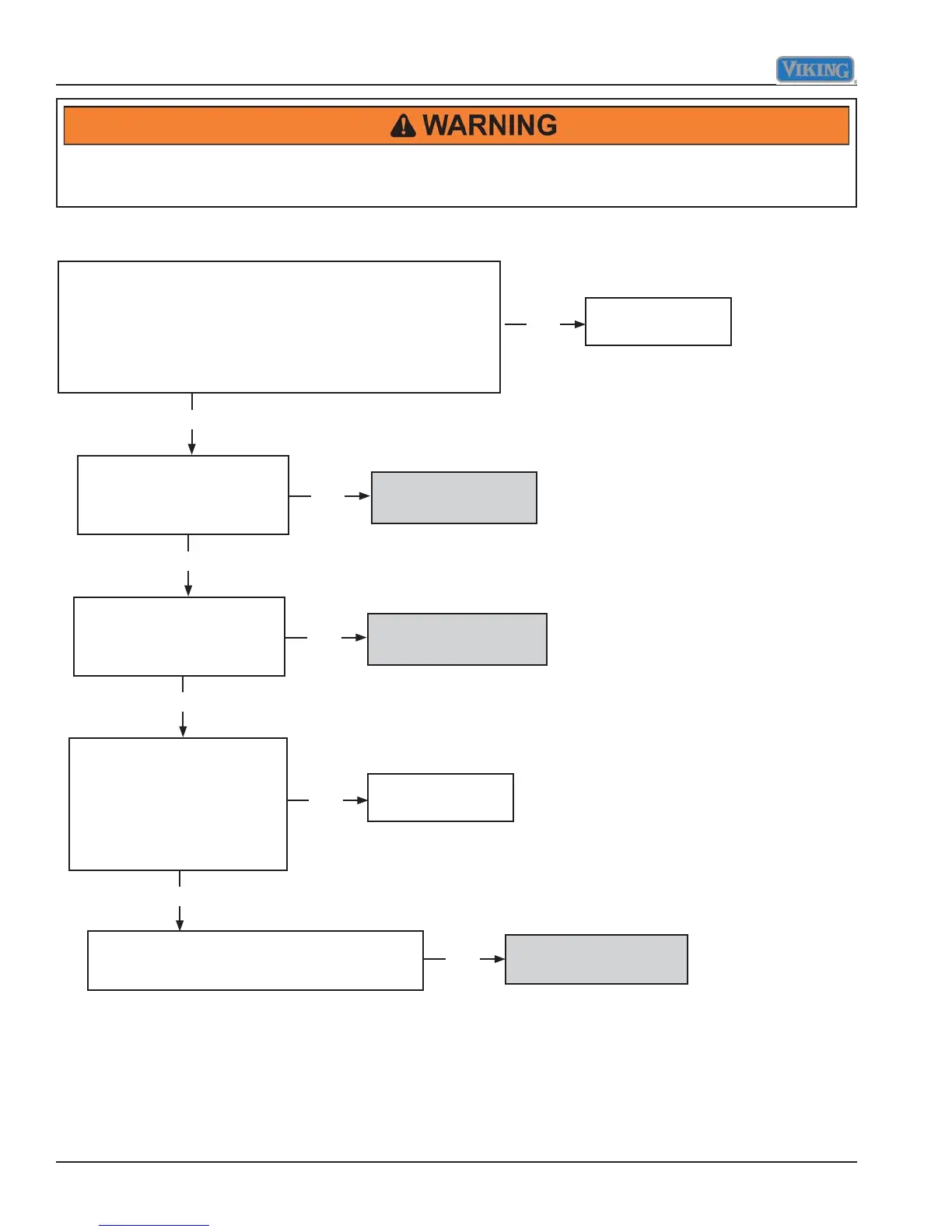
Checking Griddle Operation
Repair or replace
defective wiring.
Repair or replace
defective wiring.
Disconnect power to the range.
Access control panel and wiring.
Connect power.
120 VAC present on griddle control thermostat L1 to N?
120 VAC present on DSI module A to N?
Turn griddle control to 350°.
120 VAC present on
thermostat blue to N?
Yes
No
No
No
No
Replace thermostat.
Turn griddle control to 350°.
10.75 VAC present on
DSI module SC to S1 while
arcing?
Yes
No
Replace DSI module.
10.75 VAC present on DSI
module SC to S1 while
arcing, yet no gas present to
griddle burner? (Gas supply
valve in open position.)
Yes
Yes
Disconnect power to range.
Check griddle solenoid resistance.
210 present S1 brown to SC blue?
Replace griddle
solenoid valve.
To avoid risk of electrical shock, personal injury, or death, disconnect electrical power source to unit, unless test
procedures require power to be connected. Discharge capacitor through a resistor before attempting to service.
Ensure all ground wires are connected before certifying unit as repaired and/or operational.



 To Next Page