© 2009 Viking Preferred Service
28
Service Diagnostics and Procedures
Control Board Diagnostics (continued)
RTD Sensor
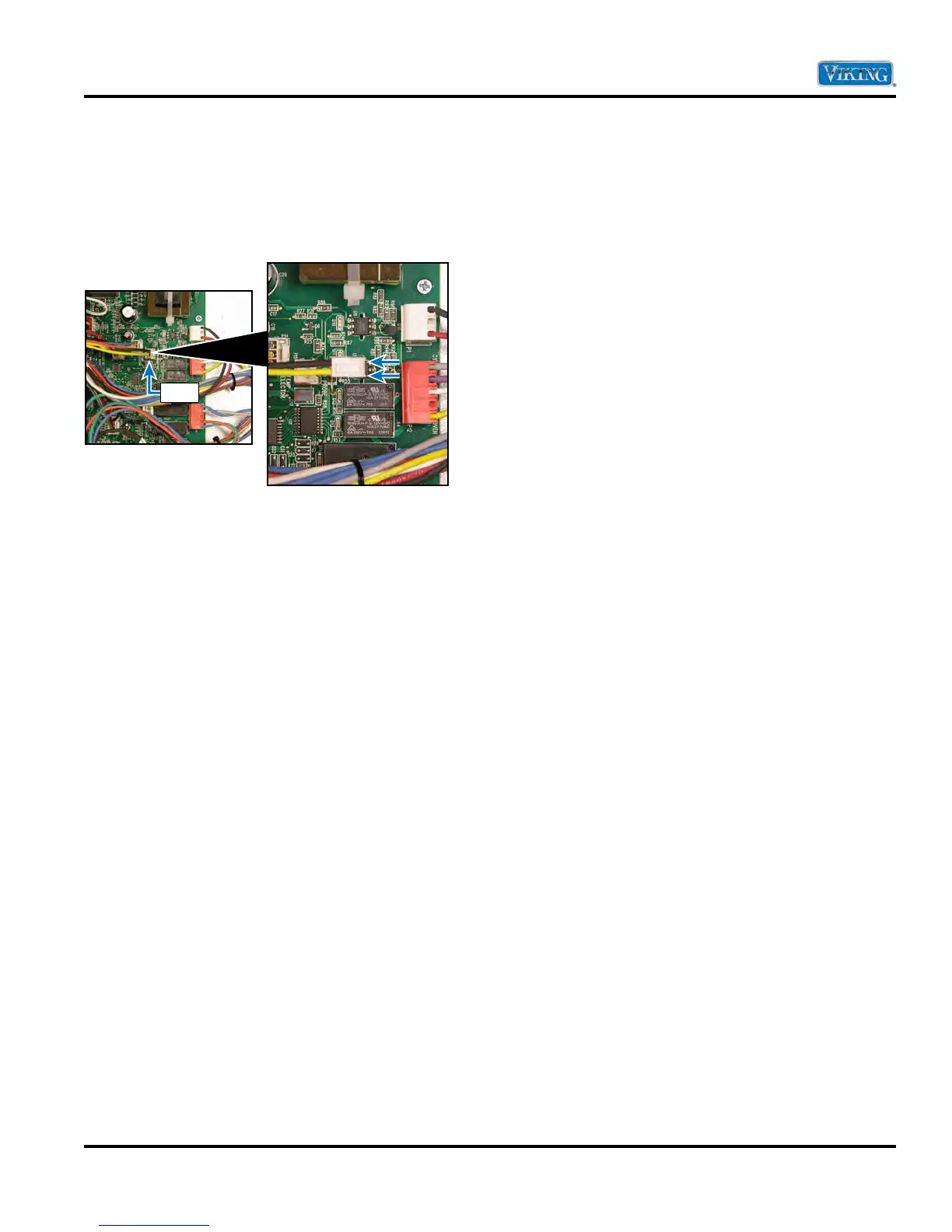
Locate the P15 connector on the main control
board. The P15 connector will have a molex plug
containing a black and yellow wire. The black and
yellow wires go to the oven sensor.
With the molex plug removed, use an Ohm meter
to measure resistance between the yellow and black
wires in the molex connector. At room temperature
the reading should be approximately 1050 – 1100 Ω.
If no or infinite resistance is read, verify sensor wiring
is connected completly throught circuit. If wiring is
OK replace sensor.
P-15


 To Next Page