34
Contents
Previous
Page
First
Page
Next
Page
Previous
View
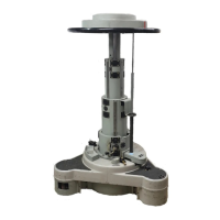
10.1 Remove two screws (3.1) securing the tilt drag adjuster arm (1) to the adjustable drag disc (3.5).
10.2 Carefully prise off the tilt drag knob boot (6.3).
10.3 Remove the tilt drag grub screw (6.1) and unscrew the tilt drag knob (6.2) and retain the washer
(4.5).
10.4 Remove the tilt brake grub screw (5.6) and remove the tilt brake lever (5.5).
10.5 Using a (UNI 5752) M 16 pin spanner, unscrew the (UNI/ISO 2982, 2983) lock ring (5.3).
10.6 Unscrew the left-hand threaded tilt brake nut (5.2) and remove the bearing (5.1).
10.7 Remove the left-hand side cover (4.3) and tilt drag assembly (3.6), (3.5) from the tilt brake shaft
(2.5). Ensure two springs (3.3) and two drag adjustment shoes (3.2) are retained.
10.8 Remove the wave washer (4.1) from the tilt brake shaft (2.5).
10.9 Remove the friction ring (4.2) from the centre housing (2.4).
10.10 Unscrew the tilt drag shaft (2.6) and remove the tilt drag adjuster arm (1).
10.11 Using an M7 allen key, unscrew the tilt brake shaft (2.5) from the centre housing (2.4) and
remove the tilt drag shaft (2.6).
10.12 If required, remove the tilt bearing sleeve (2.8). Examine the sleeve for wear and replace if
necessary.
Illumination module
11 Remove and disassemble the illumination module as follows (Fig 6.2):
11.1 Remove illumination module (9) by pressing the retaining tabs together from the underside of the
centre housing (8.2) and lifting out from above.
11.2 Push the battery (9.4) out of the illumination module from behind using a suitable pointer (pen).
11.3 Flex the plastic retaining tabs and remove the illumination PCB (9.3) from the support plate (9.2).
11.4 Carefully peel the self adhesive label (9.1) from the support plate (9.2).
12 Remove the level bubble as follows:
12.1 Remove the spring clip (8.5) and lift the level bubble (8.6) out of the centre housing (8.2).
NOTE: The M6 threaded end of the tilt drag shaft (2.6)—pre-assembled to the centre housing
(2.4)—may be spoiled by the grub screw (6.1). Either replace the tilt drag shaft with a new
one or use an M6 die-nut to clean the thread form to aid reassembly.
NOTE: The adjustable drag disc (3.5) contains 4.5 grams of Optalus A0 140 drag fluid (part no.
R116,23). If required, separate the components of the adjustable drag disc and clean.