© 1999 Directed Electronics, Inc. Vista, CA 39
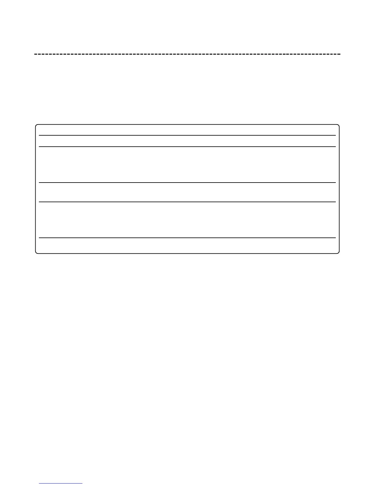
table of zones
When using the Diagnostic functions, use the Table of Zones to see which input has triggered the system. It is
also helpful in deciding which input to use when connecting optional sensors and switches.
NOTE: The Warn Away® response does not report on the LED.
ZONE NO. TRIGGER TYPE INPUT DESCRIPTION
1 Instant H1/6 BLUE wire. Connect to optional hood/trunk pins.
2 Multiplexed Input Blue wire of plug-in shock sensor. Inputs shorter than 0.8
seconds will trigger a Warn Away response, while inputs
longer than 0.8 seconds will instantly trigger full alarm
sequence.
3 Two-stage, progresses from Door switch circuit. H1/5 GREEN or H1/7 VIOLET.
warning to full alarm
4 Multiplexed Input GREEN wire of plug-in shock sensor. Inputs shorter than 0.8
seconds will trigger a Warn Away response, while inputs
longer than 0.8 seconds will instantly trigger full alarm
sequence.
5 Two-stage (similar to doors) Ignition input. H1/9 YELLOW.