Vitrek V4 – Electrical Safety Tester USER MANUAL
11
5. OPERATION METHOD
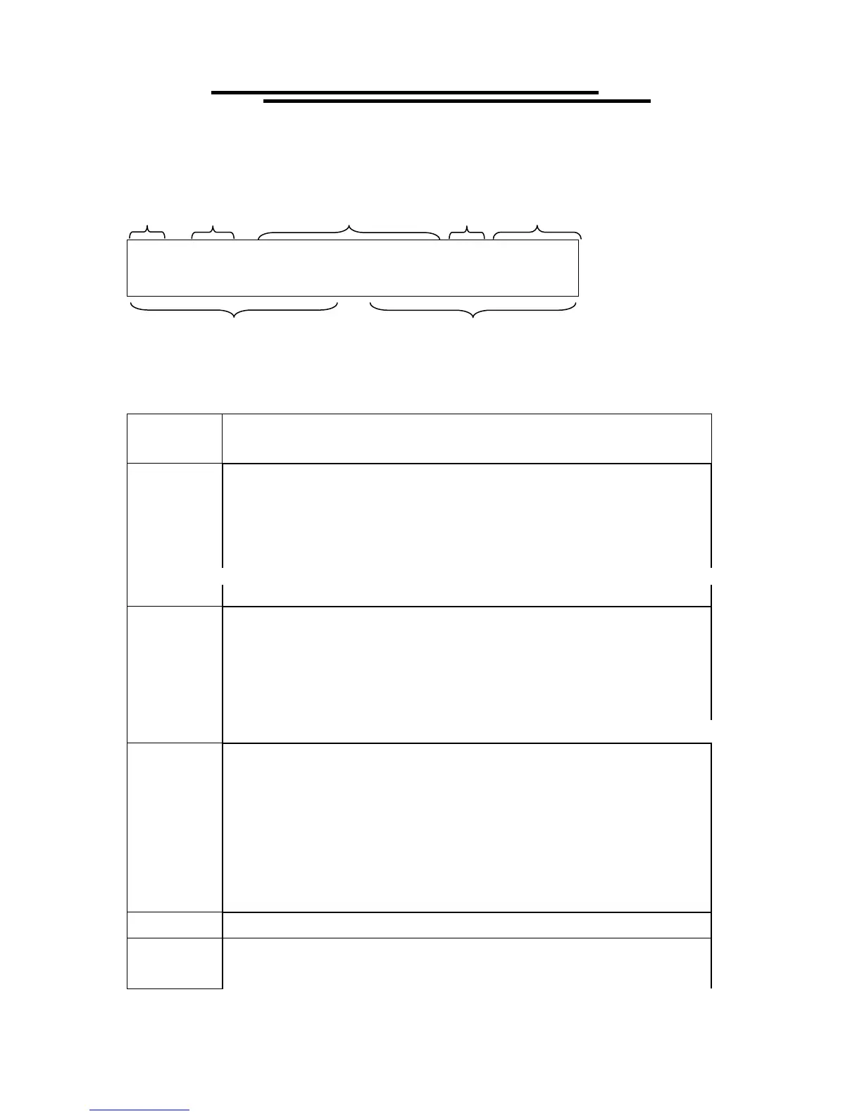
5-1. Main Display LCD
1 ~ 0 1 A C
W V = 5
. 0 0 0 k V
*
READY
I
a x = 0
1 . 0 0 m
A T E S T
:
0 0 0 . 0 s
Table of Parameters:
Storage
Group/ Step: There are total 10 groups, and each group has 16 steps. The first number
represents group while the second number represents step.
Ex. 3:1Æ 3 is for group number, 1 is for step number.
The test mode of tester includes:
ACW: AC Withstanding voltage test.
DCW: DC Withstanding voltage test.
IR: Insulation Resistance.
GB: Ground Bond test.
Mode
The total types of mode will change for different model.
Output voltage or current for each step
AC: Output voltage (0.100~ 5.000 kV)
DC: Output voltage (0.100~ 6.000 kV)
IR: Output voltage (50V/100V/500V/1000V)
GB: Output current (3.00~42.00A)
Output
Voltage/Current
The status of tester includes:
MENU: Browse and check steps of test.
EDIT: Edit parameters
SAVE: Save parameters
UTIL: Browse and check system utility.
READY: Ready for test
TEST: Testing
PASS: The result of test is pass
FAIL: The result of test is fail
Status
STOP: Stop the test
ARC
If the ARC function is enabled, the sign “*” means that there is ARC during test.
Lower and upper limit of measurement
Imax/Imin: Current measurement limit (ACW & DCW)
Measurement
Limit
Rmax/Rmin: Resistance measurement limit(IR&GB&CNT)
Storage Mode Output Voltage/Current ARC Status
Measurement Limit Ramp/Test Time