Vitrek V4 – Electrical Safety Tester USER MANUAL
22
5-5. Remote Interface Operation
For ease of automating the V4 unit when interfacing to a PC, we recommend the use the Vitrek QT50
test automation software and PC interface adaptor. The adaptor allows you to control the unit via a
standard PC serial or parallel port, while the software allows for the development of test sequences and
the storage of all test results for viewing or export to a database.
To prepare the unit for control via the remote interface press the UTILITY key and dial up the TEST
CONTOL MODE using the knob. Press the SAVE/EDIT key to edit the field and use the knob to select
MODE 3: PLC ENABLE, then press SAVE/EDIT to save the setting and press MENU to exit the utility
mode. The unit is now configured for remote operation.
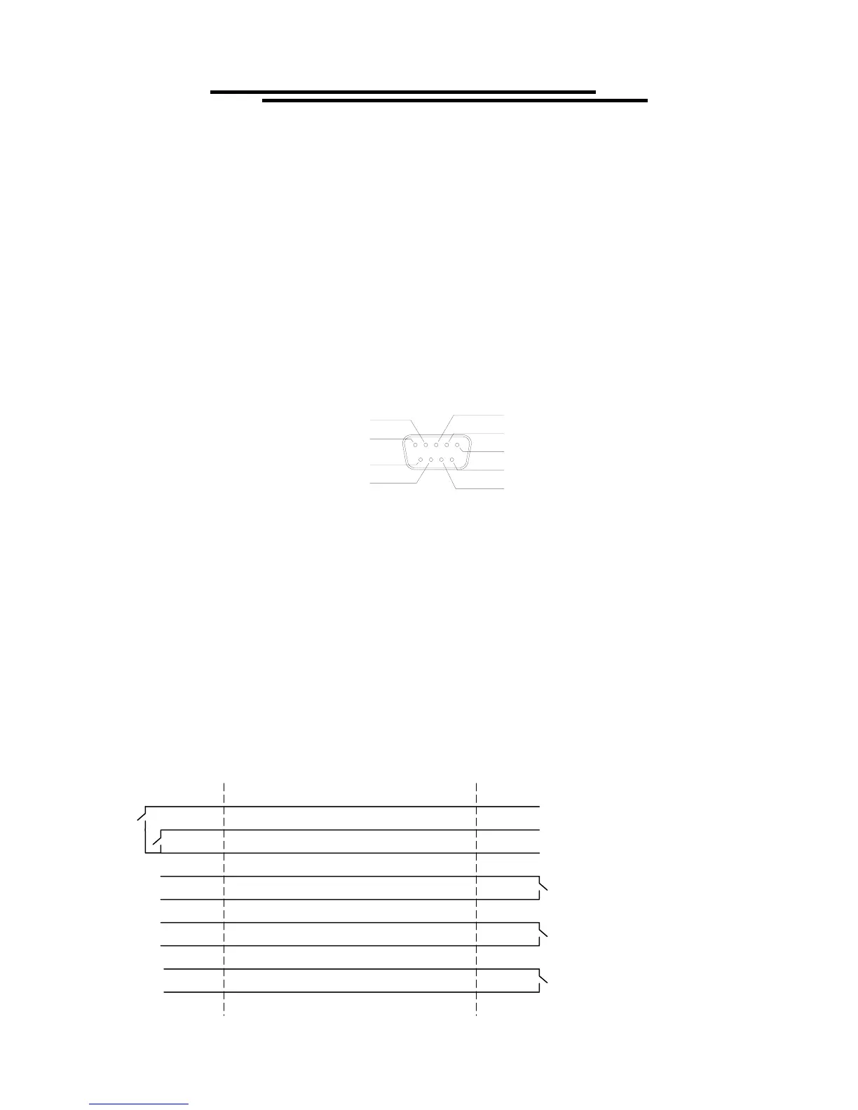
The remote interface provides two inputs (START and RESET) and three outputs (TESTING, PASS and
FAIL). The I/O connector is a DB9 FM. Output contacts are rated at 400V/ 1.3 amps maximum.
TESTING 2
TESTING 1
FAIL 1
FAIL 2
START
RESET
PASS 1
PASS 2
COMMON
RESET: Connecting “RESET”(pin 1) to “COMMON”(pin 3) will reset or interrupt this
machine (the same function as the RESET button on the front panel). A reset is
required to clear the pass/fail status and place the tester in the ready mode.
START: In status READY, connecting “TEST”(pin 2) to “COMMON”(pin 3) will start the test
procedure (the same functionality as the START button in the front panel).
TESTING 1,2 : While testing, the “TESTING” lines will be shorted and will remain shorted until the
pass/fail contacts are set.
PASS 1, 2: If the result of the test is “pass”, the “PASS 1” and “PASS 2”(pins 6 & 7) will be
shorted.
FAIL 1, 2: If the result of the test is “fail”, the “FAIL 1 and “FAIL 2”(pins 8 & 9) will be shorted.
The pass/fail results will remain valid until the reset is activated.
RESET (pin 1)
START (pin 2)
COMMON (pin 3)
TESTING1 (pin 4)
TESTING2 (pin 5)
PASS1 (pin 6)
PASS2 (pin 7)
FAIL1 (pin 8)
FAIL2 (pin 9)
EST REMOTE
INTERFACE
REMOTE
CONTROLLER