Vitrek V4 – Electrical Safety Tester USER MANUAL
23
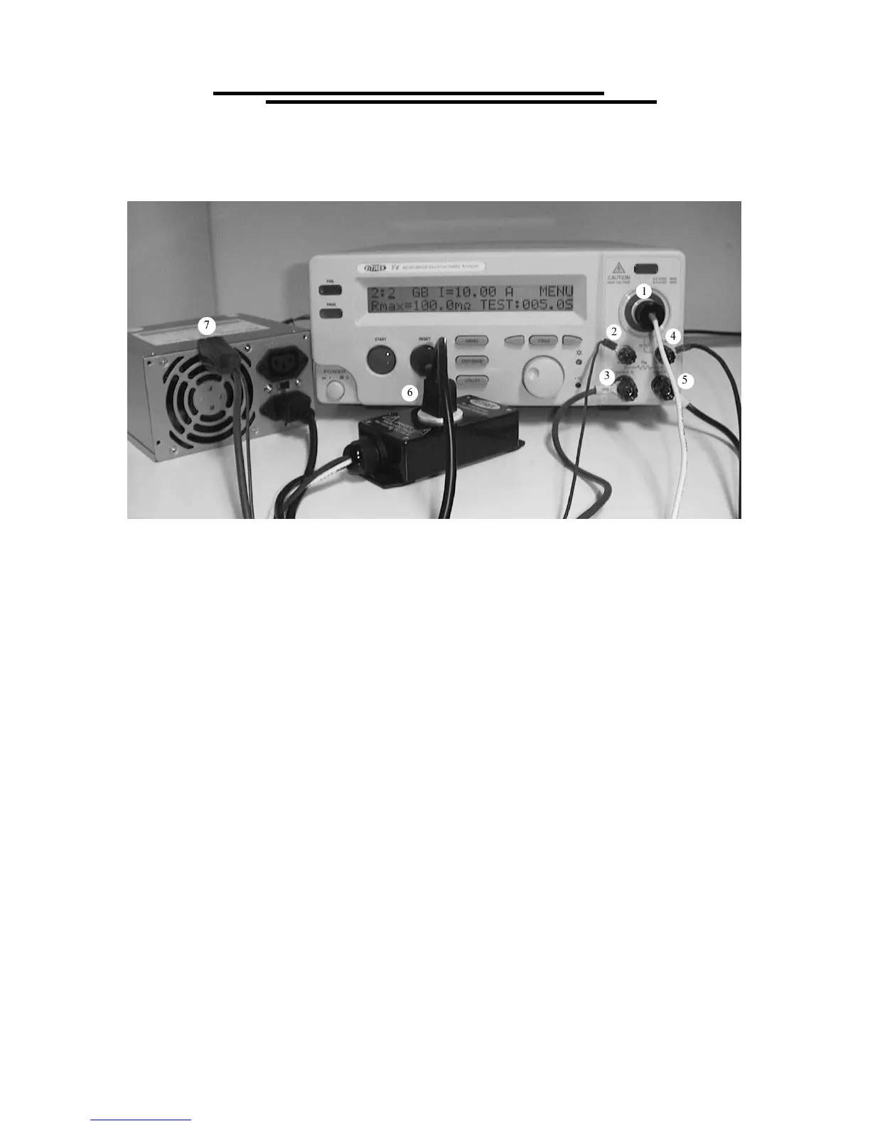
6. MEASUREMENT CONNECTIONS
ACW, DCW and/or IR Test Connections
Terminal 1 shown above is the High Voltage Output Terminal. This large HV connector with a red
circle around it is the output terminal for all HV tests (ACW, DCW and IR). For typical electrical
safety testing, this terminal connects to both the line and neutral power pins of the device under test
(DUT). For devices using a NEMA 5-15 (North American) power plug the available TL-115-4 shown
above provides for quick and convenient connection. CAUTION: The HV terminal is capable of
delivering up to 5kVAC or 6kVDC. Use only with HV rated lead material and avoid contact with the
terminal, test leads and the DUT when high voltage is present on this terminal.
Terminal 4 shown above is the Sense (-)/Return Terminal. The sense (-)/return terminal is the
reference terminal for leakage current measurement. This terminal typically connects to the earth
ground pin of the DUT. Inside the TL-115-4and the TL-IEC-4 this terminal is connected to the earth
socket of the test adapter. These are the only two terminals used to make the above test
Ground Bond Only Test Connections
Terminals 4 & 5 Sense (-) and Source (-) connect to the DUT earth ground pin.
Terminals 2 & 3 Sense (+) and Source (+) connect to a conductive portion of the DUT Chassis.
Combined ACW, DCW and/or IR with Ground Bond Test Connections
Terminal 1 HV Output Terminal, connects to both the line and neutral power pins of the DUT
Terminals 4 & 5 Sense (-) and Source (-) connect to the DUT earth ground pin.
Terminals 2 & 3 Sense (+) and Source (+) connect to a conductive portion of the DUT Chassis.
Note: Source terminals require 10AWG or larger conductor lead wire.