Vitrek V4 – Electrical Safety Tester USER MANUAL
24
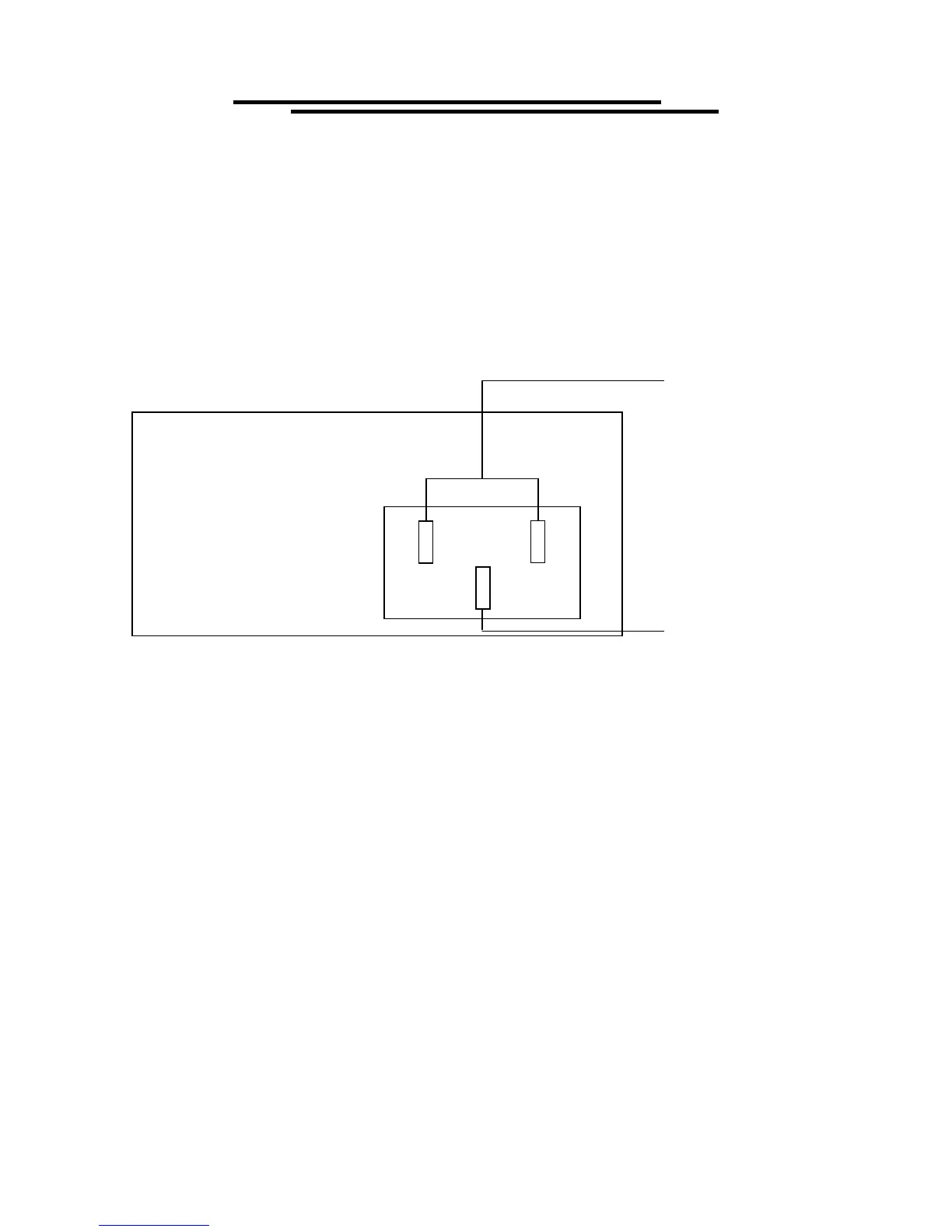
Typical Electrical Safety Test Connection Diagram
7. PROGRAMMING
7-1. Introduction
The Vitrek V4 Electrical Safety Tester (EST) is a fully interactive automatic measurement system.
Communication between the V4 and host computers is easily accomplished. The V4’s standard RS232
interface or optional GPIB interface provide the capability to download and run a custom test sequence,
as well as, monitor the status of the test and retrieve results and actual readings.
Interface selection and setup:
The GPIB address and RS232 baud rate can be changed in normal operation condition. Press [UTILITY]
key and knob switch or arrow keys on the front panel, in which the last transmitting interface settings
will be displayed. Select interface and press [EDIT/SAVE], then select the baud rate (or GPIB address)
and press [FIELD] to confirm the setting. Finally, press [EDIT/SAVE] to store the setup.
7-2. Connecting the V4 via GPIB Interface
The GPIB interface capabilities:
The GPIB interface of the V4 corresponds to the standard of IEEE488.1-1987, IEEE488.2-1992 and
SCPI-1994. The GPIB interface functions are listed as follows:
SH1 (Source Handshake): The EST can transmit multilane messages across the GPIB.
DUT CHASSIS
Connects to Source + & Sense +
For Ground Bond
TO HV TERMINAL
For ACW, DCW or IR
TO SENSE -/ RETURN
(FOR GB CONNECT
SOURCE – ALSO)
DEVICE UNDER TEST
L
E