Vitrek V4 – Electrical Safety Tester USER MANUAL
28
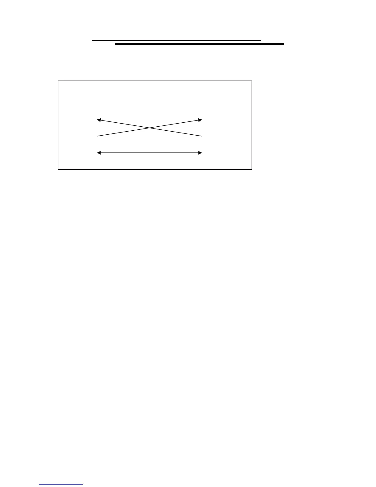
EQUIPMENT
(DB9, DTE)
COMPUTER
(DB9, DTE)
Pin2
Pin3
Pin5 Pin5
Pin3
Pin2
Wiring configurations for DB9 to DB9:
Computer’s Connection
A personal computer with a COM port is the essential facilities in order to operate the V4 via
RS232 interface. The connections between EST and computer are as follows:
1. Connect one end of a RS232 cable to the computer.
2. Connect the other end of the cable to the RS232 port on the V4.
3. Turn on the V4.
4. Turn on the computer.
The RS232 connection testing:
If you want to test whether the RS232 connection is working or not, you can send a command from
computer. For instance, using a terminal program send the query command
*idn?
should return the Manufacturer, model number, serial number and firmware version in the following
format:
Vitrek.Inc,V63,0,FW1.20 or Vitrek.Inc,V4,0,FW1.20
If you do not receive a proper response from the EST, please check if the power is on, the RS232 baud
rate are the same on both sides, and all cable connections are active.
7-4. Input and Output Queue
The design of 128 bytes input queue and 128 bytes output queue for storing the pending commands or
return messages is to prevent the transmitted commands of remote control and return messages from
missing. As the maximum stored capacity for Error/Event Queue is 20 groups of messages, it should be
noted that input data exceeding the capacity by using these buffers would cause data missing.
7-5. Commands and Syntax
The GPIB commands of the V4 are compatible with IEEE-488.2 and SCPI standards
SCPI (Standard Commands for Programmable Instruments) is a standard that created by an
international consortium of the major test and measurement equipment manufacturers. The IEEE-488.2