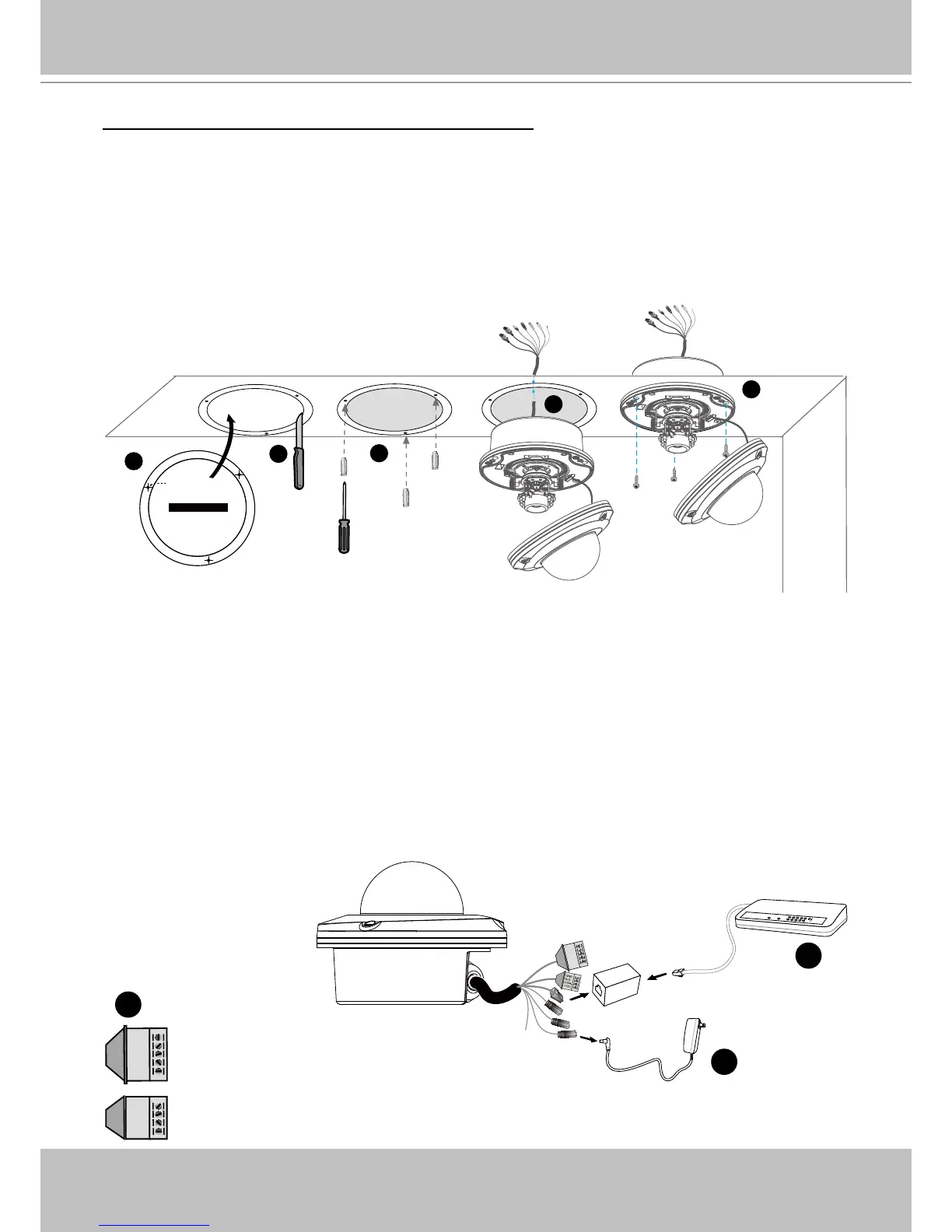
Ceiling mount without the bottom base (Embedded)
1� Attach the supplied ceiling hole template sticker to the ceiling�
2� Open a hole along the inner circle of the sticker�
3� Using the 3 circles on the sticker, drill 3 pilot holes into the ceiling� Then hammer the three
supplied plastic anchors into the holes�
4� Mount the Network Camera to the ceiling and feed the cables through�
5� Using the three holes on the side of the camera base, insert the three supplied screws into
the corresponding holes and secure them with a screwdriver�
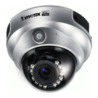
Network Deployment
Setup the Network Camera over the Internet
This section explains how to congure the Network Camera to an Internet connection�
1� If you have external devices such as sensors and alarms, make the connection from the
general I/O terminal block�
2� Use the supplied RJ45 female/female coupler to connect the Network Camera to a switch.
Use a Category 5 Cross Cable when Network Camera is directly connected to PC�
3� Connect the power cable from the Network Camera to a power outlet�