VIVOTEK
110 - User's Manual
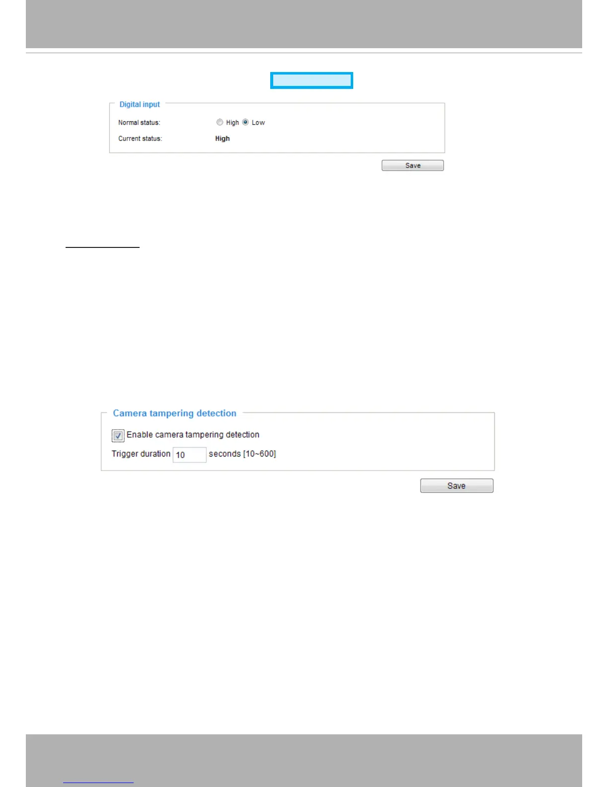
Applications > Digital Input
Connect a DI device to the camera's push-in type terminal block, the camera will automatically
detect
the current connection state as pulled-high or pulled-low� You may then define the
triggering condition�
Normal status: Select High or Low to define the "Normal status" for the digital input. The
Network Camera will report the current status below�
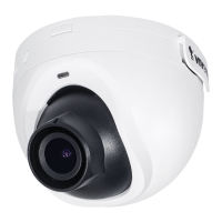
Applications > Tampering detection
This section explains how to set up camera tamper detection� With tamper detection, the
camera is capable of detecting incidents such as redirection, blocking or defocusing, or even
spray paint
�
Please follow the steps below to set up the camera tamper detection function:
1� Check Enable camera tampering detection�
2� Enter the tamper trigger duration� (10 sec� ~ 10 min�) The tamper alarm will be triggered only
when the tampering factor (the difference between current frame and pre-saved background)
exceeds the trigger threshold�
3� You can configure Tampering Detection as a trigger element to the proactive event
configurations in Event -> Event settings -> Trigger. For example, when the camera is
tampered with, camera can be configured to send pre- and post-event video clips to a
networked storage device� Please refer to page 112 for detailed information�
Advanced Mode