EN-4
3-2. Connecting Power and I/O Wires
If you need to connect I/O wires and 24V power, disassemble the top section of the
camera. It is highly recommended to complete the following before you can mount
the speed dome camera at the installation site:
Skip this section and move to Section 3-3 if you connect the Ethernet cable only.
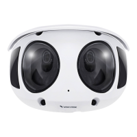
1-3
1-2
1-1
Plan the wire length and complete cabling to
the Interface Section
Cabling through the dome cap and waterproof
connectors
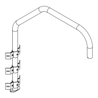
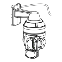
Connect with the mount bracket
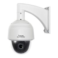
3-2-1. Cabling through the Waterproof Connectors
Components of the Waterproof Connector
Seals (C)
Housing (D)
Sealing Nut (E)
Seal (B)
Screw Nut (A)
•
Wire range: 13~16AWG (1.2~1.8mm)
•
A socket wrench for the M20 hex nut is
required.