WBV.PU.002.EN VX136Q V2.0
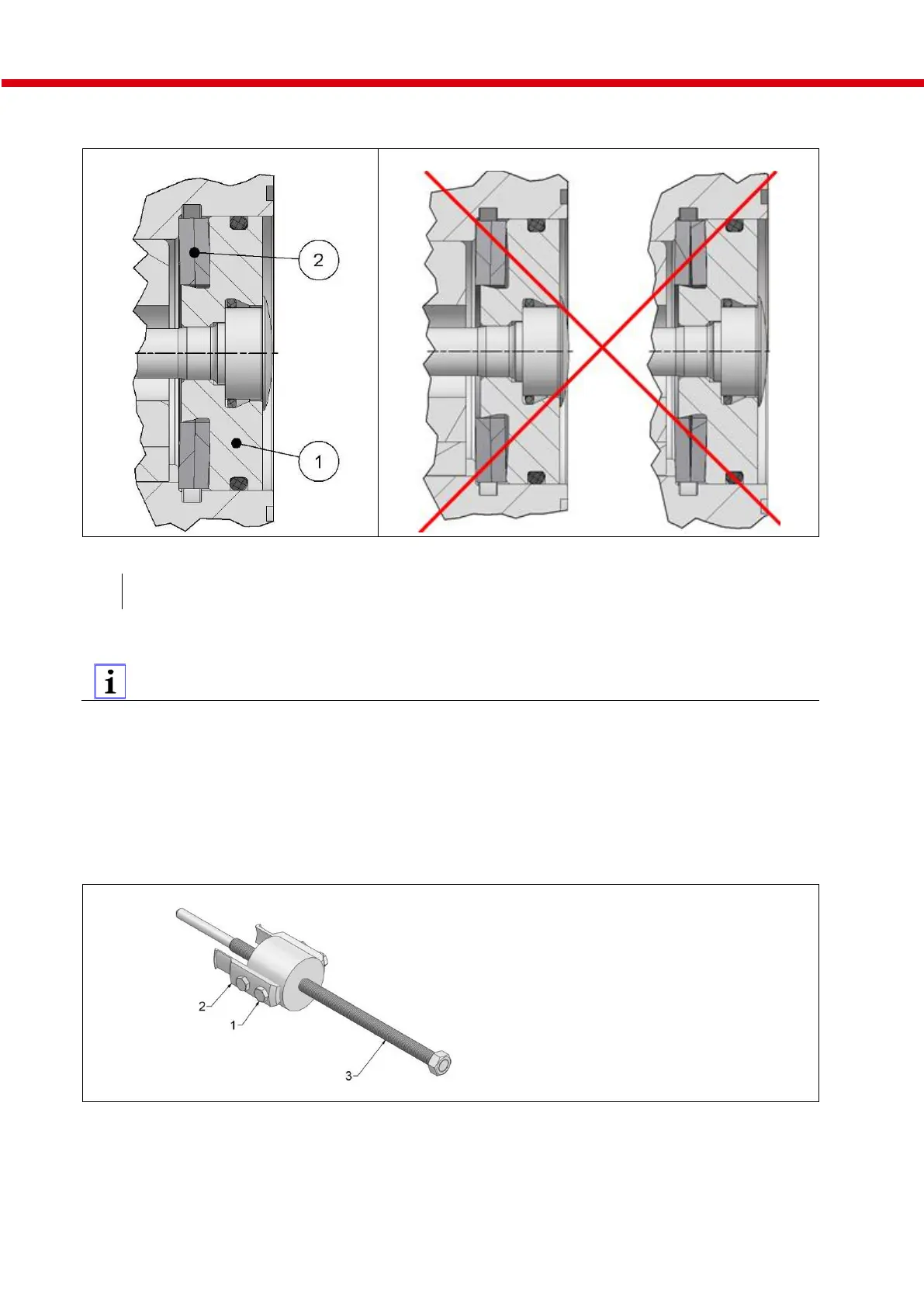
Position of pressure disc and spring washer
Attention! Incorrect assembly:
Fig. 24: Position of pressure disc and spring washer
Spring washers (two per shaft)
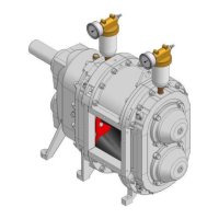
9.4 How the lobe puller works
We recommend using two lobe pullers so the upper and lower lobes can be pulled off as simultaneously as
possible.
VX136-70/105Q: part no. PBA.B001.TK
VX136-140/210Q: part no. PBA.B001.TL
Alternatively:
Combination tool for lobe change and Cartridge mechanical seal change
of all VX136Q pump sizes: part no. PBA.B033.T1
Fig. 25: Lobe puller components
1. Undo the four hexagon head bolts (1) so that the puller arms (2) can be moved.
2. Hook the two puller arms (2) into the groove provided on the lobe Fig. "Hooking puller arm into
lobe".
3. Tighten the hexagon head bolts (1) with approx. 50 Nm.