20
Voith Turbo H + L Hydraulic GmbH & Co. KG
25000057510-TED-ENX-04
5 Voith internal gear pumps
This section contains a description of the components and functionality of internal
gear pumps.
5.1 Designandfunctionality
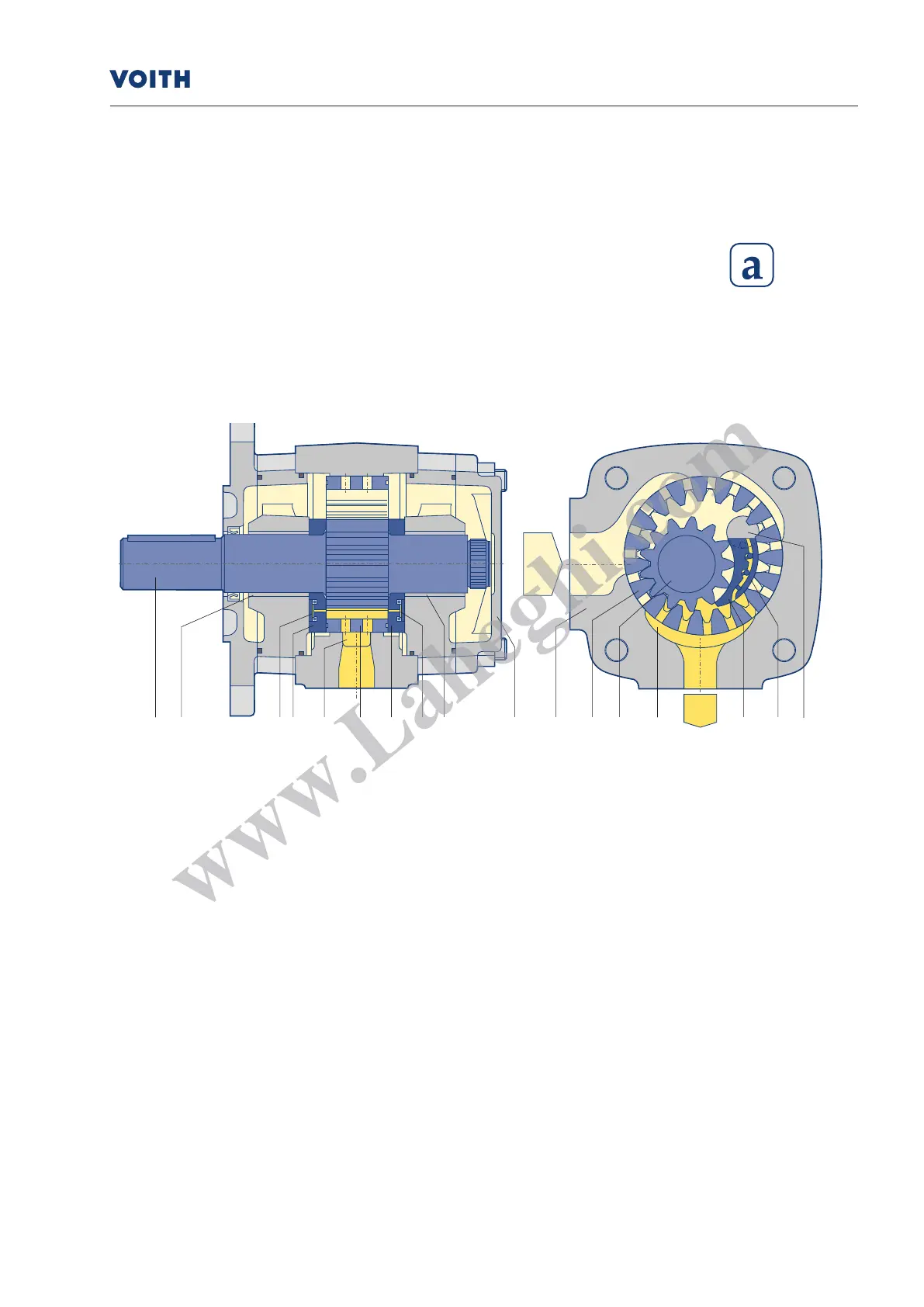
5.1.1Sickleprinciple
Fig. 5.1.1: Components of internal gear pump with sickle principle
When the gears rotate in the pump the pressure uid (as a rule hydraulic oil) is drawn
into the cavity between the pinion and internal gear. The two smoothly running gears
help to ensure excellent intake behavior.
In the radial direction, the gear chambers are sealed by gear meshing and/or the ller
piece. In the axial direction, the axial plates seal the pressure chamber with the minimal
possible gap. This design minimizes volume losses and increases efciency. When the
gears rotate, the pinion teeth enter the gaps between the internal gear teeth and
displace the pressure uid.
Individual pumps suck via the radial suction port on the pump housing. With two-ow
and multi-ow pumps, suction is generally possible via the suction port on the interim
housing. For low-noise operation of the pumps, the low pump ow and pressure pulsa-
tion usually help.
1 Pinion shaft
2 Internal gear
3 Filler pin
4a Filler segment carrier
4b Filler sealing segment
5 Axial disc
6 Axial pressure area
7 Plain bearings
8 Housing
9 Hydrostatic bearing
10 End cover
1 7 6 5 9 2 5 6 7 10 8 2 1 9 4a 4b 3
Internal gear pumps
Design and functionality