Group 25 Intake and Exhaust System Design and Function
Control System
The engine brake is connected to the throttle pedal and
is activated when the pedal is completely released, ac-
cording to the selection made with the engine brake
switch on the instrument panel.
The selection made with this switch also regulates en-
gine braking activated by the cruise control.
Note: The engine brake functions as long as the engine
control system has received signals from engine sensors
indicating that the required preconditions for engine
braking have been met. For example, the engine speed
must be greater than 1100 rpm, the vehicle speed must
be greater than 12 km/h (7.5 mph), and the engine tem-
perature must be above 70
C (160
F).
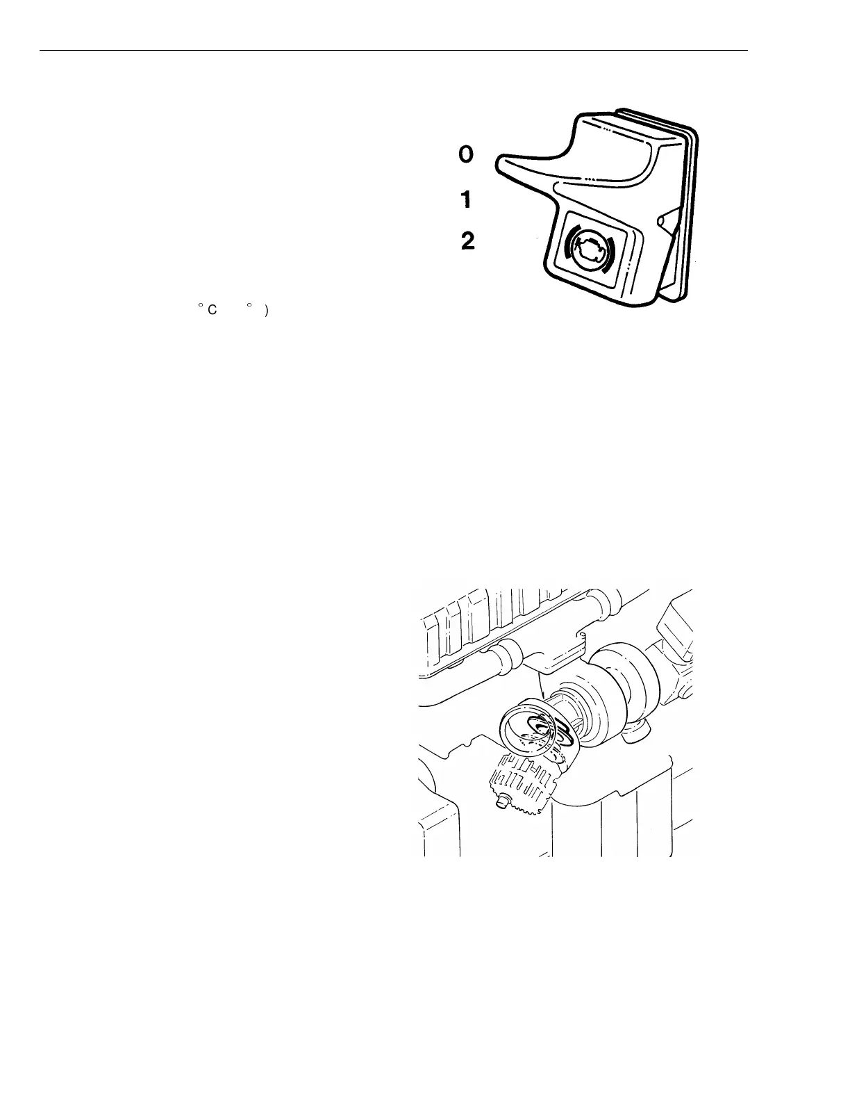
The switch has three positions:
0 No engine brake engaged
1 Exhaust brake, EPG
2 Exhaust brake and compression brake, VEB
T2006953
Fig. 10: Switch for engine brake
Exhaust Brake
When exhaust braking, the exhaust pressure governor
(EPG) is activated with a control pressure of approxi-
mately 750 kPa (110 psi). At this point, the shutter is
forced out of the EPG and into the shutter housing. This
restricts the flow of exhaust gases out of the cylinders,
as the shutter blocks the outlet from the turbocharger.
Restricting the flow of exhaust gases forms an air cush-
ion between the shutter and the piston crowns. During
the exhaust stroke, this air cushion provides a braking
effect on the pistons as the exhaust valves are then
opened.
The higher the engine speed during the exhaust braking,
the greater the braking effect.
T2006832
Fig. 11: Exhaust pressure governor
16