EMB-9670/9673 Series
44 EMB-9670/9673 Series User’s Manual
2.3.18 Signal Description – Serial Port 3 / 4 / 5 / 6 with External DB9 Connector
(JCOM36)
Signal Signal Description
TxD
Serial output. This signal sends serial data to the communication link. The signal is
set to a marking state on hardware reset when the transmitter is empty or when
loop mode operation is initiated.
RxD Serial input. This signal receives serial data from the communication link.
DTR
Data Terminal Ready. This signal indicates to the modem or data set that the
on-board UART is ready to establish a communication link.
DSR
Data Set Ready. This signal indicates that the modem or data set is ready to
establish a communication link.
RTS
Request To Send. This signal indicates to the modem or data set that the on-board
UART is ready to exchange data.
CTS
Clear To Send. This signal indicates that the modem or data set is ready to
exchange data.
DCD
Data Carrier Detect. This signal indicates that the modem or data set has detected
the data carrier.
RI
Ring Indicator. This signal indicates that the modem has received a telephone
ringing signal.
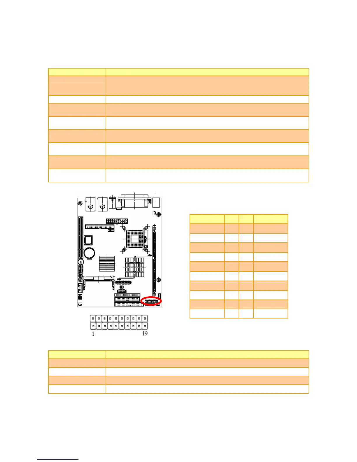
2.3.19 DI/O Connector (JDIO)
Signal PIN PIN Signal
DO_1 1 2 DI_1
DO_2 3 4 DI_2
DO_3 5 6 DI_3
DO_4 7 8 DI_4
DO_5 9 10 DI_5
DO_6 11 12 DI_6
DO_7 13 14 DI_7
DO_8 15 16 DI_8
SMB_CLK 17 18 SMB_DATA
GND 19 20 +5V
2.3.20 Signal Description – DI/O (JDIO)
Signal Signal Description
DI [7:0] Digital Input Data Bit 7 to Bit 0
D0 [7:0] Digital Output Data Bit 7 to Bit 0
SMB_CLK Data input for I
2
C input, 5V tolerant
SMB_DATA Data input for I
2
C serial input, 5V tolerant
 Loading...