User’s Manual
EMB-9670/9673 Series User’s Manual
45
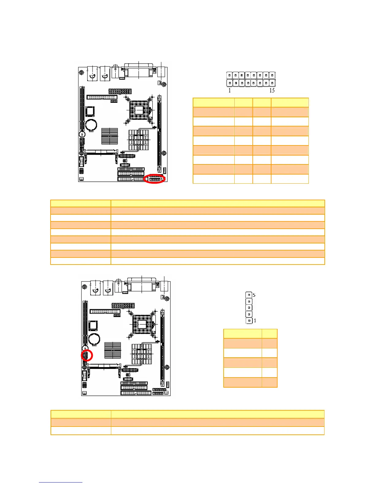
2.3.21 Front Panel Connector (JFP)
Signal PIN PIN Signal
RESET 1 2 SYS_LED+
GND 3 4 SYS_LED-
HDD_LED+ 5 6 PWR_LED+
HDD_LED- 7 8 PWR_LED-
VCCSB 9 10 VCCSB
PWR_BUT 11 12 SUS_LED
SUS_BUT 13 14 SPK+
GND 15 16 SPK-
2.3.22 Signal Description – Front Panel Connector (JFP)
PIN No. Description
1, 3 Reset SW
2, 4 System LED
5, 7 HDD LED
6, 8 Power LED
9, 11 Power SW
10, 12 Suspend LED
13, 15 Suspend SW
14, 16 Speaker
2.3.23 IrDA Connector (JIR)
Signal PIN
IRTX 5
GND 4
IRRX 3
NC 2
+5V 1
2.3.24 Signal Description – IrDA Connector (JIR)
Signal Signal Description
IRRX Infrared Receiver input
IRTX Infrared Transmitter output
 Loading...