5.4 Using Trigger and Strobe
Depending on your camera model, the pins for trigger and strobe are located on dif-
ferent connectors. The following tables show the different connectors and the cor-
responding pinouts for trigger and strobe. If you are not sure about the location of the
connectors, please refer to 2.2 on page 10.
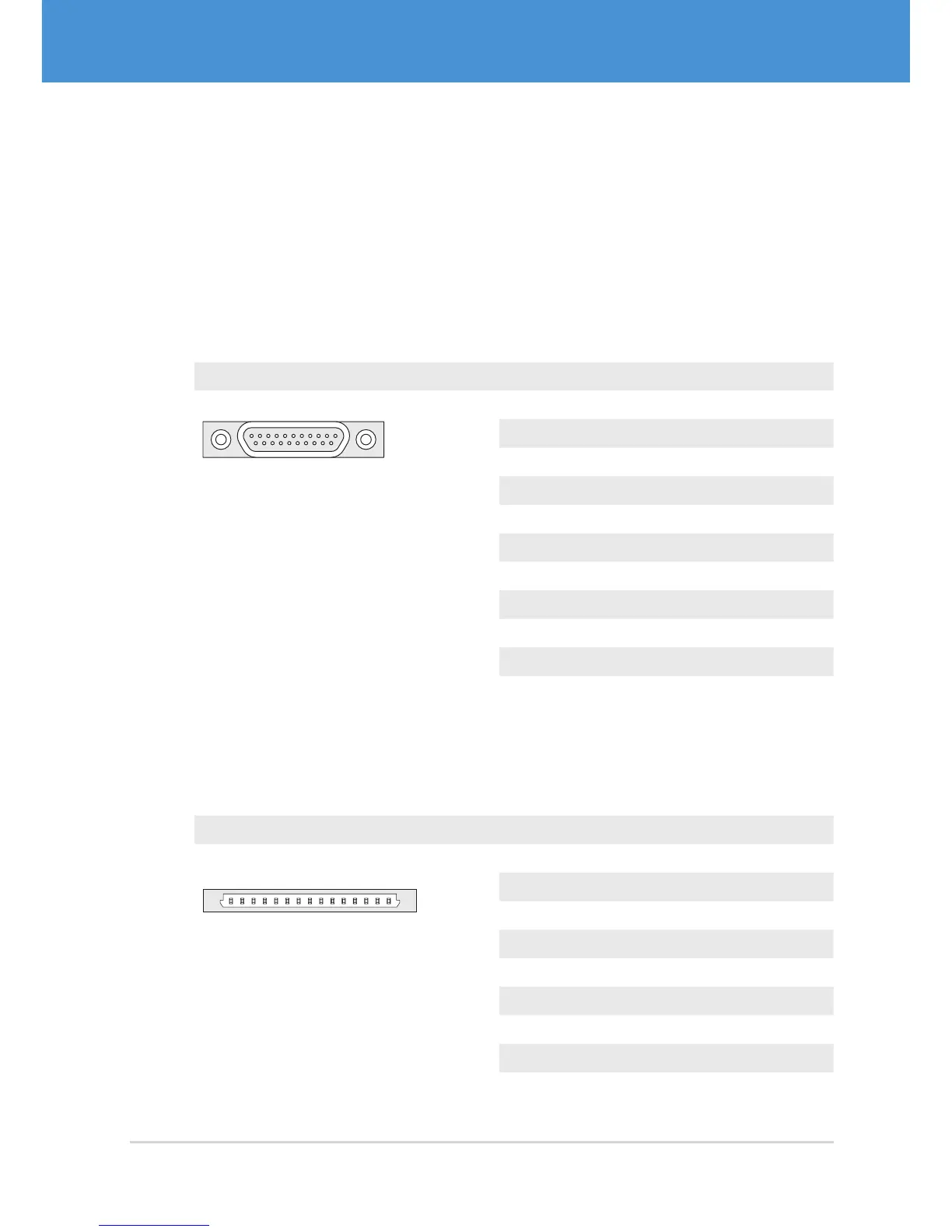
Single-Sensor Housing Cameras
Camera models: VRm(F)C-X-PRO
Connector Pin Signal
1 11
12 21
MPE Garry Micro-T 386-2-021-ZS0
1 GND
2 Passive Strobe Out– (3...24 V)
3 Passive Strobe Out+ (3...24 V)
4 Active Strobe Out (+5 V)
5 GND
6 Passive Trigger In– (3...24 V)
7 Passive Trigger In + (3...24 V)
8 Active Trigger In (+3.3...5 V)
9 GND
10...11 +5 V
12...21 ...
Single-Sensor Board-Level Cameras, Remote-Sensor Cameras,
Multi-Sensor Cameras
Camera Models: VRm(F)C-X-OEM/COB, VRmC-X-E, VRmMFC
Connector Pin Signal
5
Hirose DF14-15P
1...2 +5 V
3 GND
4...7 reserved
8 GND
9 Active Trigger In (+3.3...5 V)
10 Active Strobe Out (+5 V)
11...12 reserved
13 GND
14...15 reserved
29USB Cameras – User Guide
First Steps