S
4
3
2
1
4-pin header
1 Active Strobe Out (+5 V)
2 GND
3 GND
4 Active Trigger In (+3.3...5 V)
5.4.1 Trigger Input
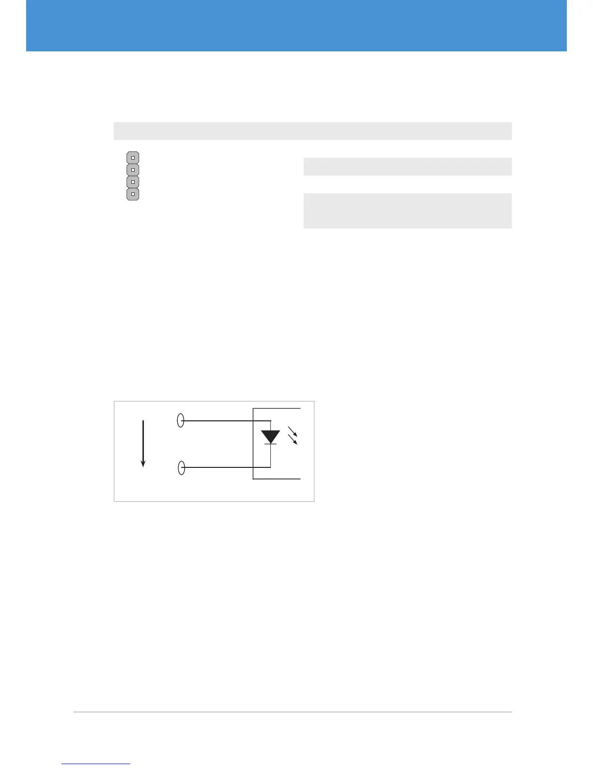
Passive Trigger Input (potential-free)
The passive trigger input accepts a positive voltage (3...24 V). The signal will be inter-
preted as logically high when the voltage exceeds 3 V, and as logically low when the
voltage drops below 1V. The current flowing between TriggerIn+ and TriggerIn– is
approx. 2 mA at 3.3 V and approx. 5 mA at 24 V. The active and the passive trigger input
are connected internally and cannot be controlled separately.
3.3V...24V
TriggerIn +
TriggerIn –
Passive Trigger Input
Fig. 17: Passive Trigger Input
Active Trigger Input (TTL)
An LVTTL/TTL compatible signal can be fed in at the active trigger input in reference
to GND. The input features an internal pull-down resistor, input current max. 1 mA.
USB Cameras – User Guide30