7.3 Cable Plan VRmC-X PRO Interface Cable
1 11
12 21
...
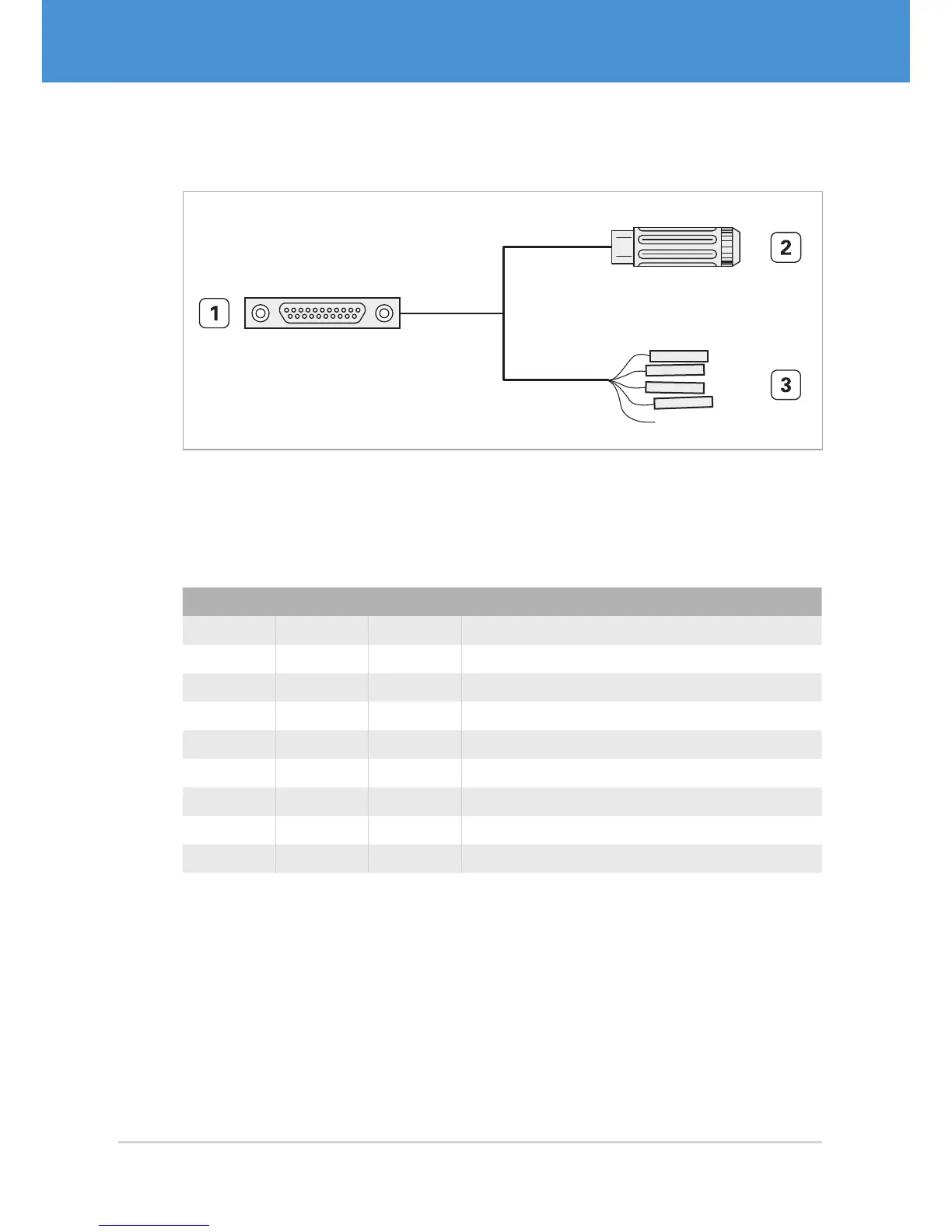
Fig. 22: VRmC-X PRO interface cable for PRO cameras
1 MPE Garry Micro-T 387-1-021-ZS0, to be plugged into camera receptacle
2 Switchcraft PC722A receptacle for 5 V power supply
3 Receptacles for 0.1” connector (7 pieces)
#2 pin #3 wire #1 pin Signal
ring 5, 9 GND
center pin 10, 11 +5 V DC (±5%) in / VBUS out
white 1 GND
brown 2 StrobeOut – (potential-free)
green 3 StrobeOut + (potential-free)
yellow 4 TTL StrobeOut (+5 V)
gray 6 TriggerIn – (potential-free)
pink 7 TriggerIn + (potential-free)
blue 8 TTL TriggerIn (+3.3...5 V)
USB Cameras – User Guide36