57
Appendix
8
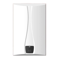
Remove two sealing packings from the silence.
Sealing packing
Silence
9
Replace the gas connector and the gas inlet pipe to its original
position and secure all connections.
Check the gas leakage before operating the water heater.
10
Turn on the gas and water supply to the water heater.
11
Set the DIP switch to minimum heat capacity operation.
Danger
Be sure to turn off the power before changing the DIP
switch setting
Notice
For more information about setting the DIP switches, refer to
"Setting the DIP Switches" on page 47.
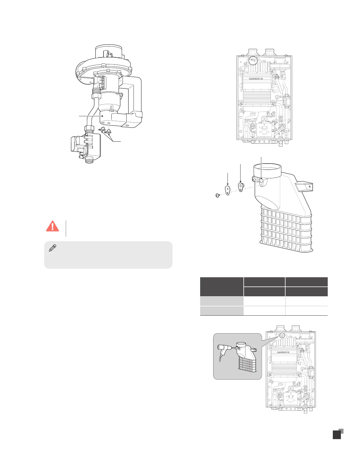
12
Loosen the screw, remove the bracket and the cap to access
the exhaust analyzer hole.
Exhaust analyzer hole
Cap
Bracket
13
Insert analyzer into the exhaust analyzer hole and measure the
gas/air ratio (using combustion analyzer is recommended).
Type
High fire Low fire
CO
2
(%) CO
2
(%)
NG 9.5 ± 0.5 9.9 ± 0.5
LPG 9.5 ± 0.5 11.5 ± 0.5