TEBS E
5
braking system
31
Components / Part number Application / Vehicle type Purpose/Function
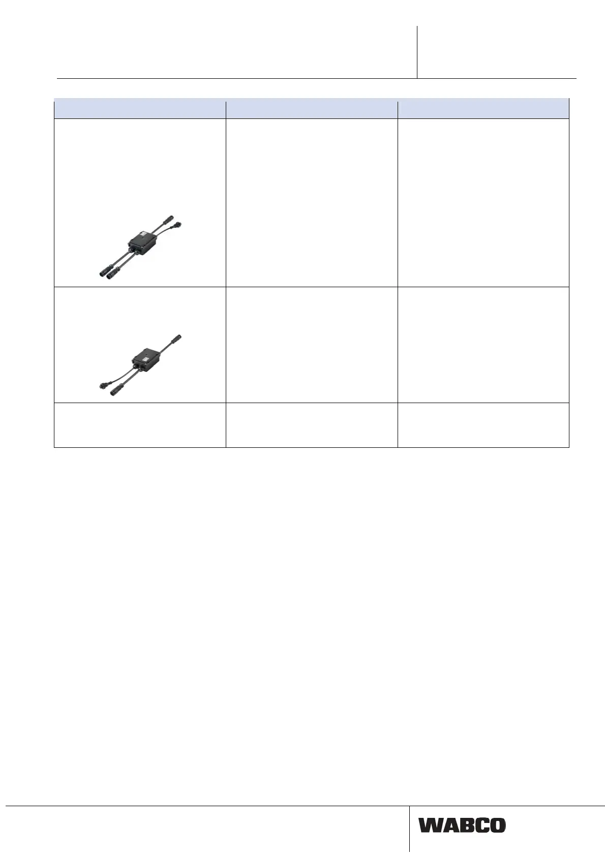
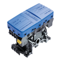
CAN router
446 122 050 0 (Socket)
446 122 056 0 (Socket; with connection
for nominal pressure sensor)
446 122 052 0 (Connector)
446 122 054 0 (Connector; with connec-
tion for nominal pressure sensor)
Tractor trailers with multiple trailer brak-
ing systems (EuroCombis or road
trains).
Between towing vehicle/trailer interface
and TEBS E Modulator(s).
Power supply and distribution of CAN
signals to multiple TEBS E Modulators.
Up to four CAN routers in series can
supply up to five TEBS E Modulators.
By connecting an optional pressure
sensor, the brake/control pressure is
measured in the vicinity of the coupling
head and is sent as a CAN signal to the
TEBS E Modulator(s) connected to the
outputs, to guarantee optimal response
time even without an EBS towing vehi-
cle.
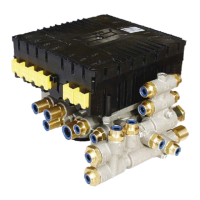
CAN repeater
446 122 051 0 (Socket)
446 122 053 0 (Connector)
For special vehicles, the cable lengths
of which do not correspond with regula-
tions, e.g. telescoping low-beds or long-
log transporters.
Between towing vehicle/trailer interface
and TEBS E Modulator.
Amplification of the CAN signal to en-
sure information supply for the con-
nected TEBS E over greater distances.
Note: ISO 11992 stipulates that the line
in the trailer be maximum 18 m. The
cable length for Trailer EBS E together
with the CAN repeater can be up to
80 m.
Cable
Cable overview, see chapter 12.3 ‘Cable
overview’, page 201.
Connecting components
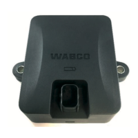
5.6 Components of the TEBS E Modulator
The TEBS E Modulator is controller electronics with four input channels for rota-
tional-speed sensors and one CAN interface ‘Towing vehicle’.
The components of the modulator are:
• An internal pressure sensor ‘Braking pressure’
• An internal pressure sensor ‘Axle load’
• A backup valve for emergency operation if the power fails
• Two modulators for controlling the brake cylinders
• Two internal pressure sensors for measuring the pressures for the brake cylin-
der
• One control output for controlling another axle
• One internal pressure sensor for monitoring the supply pressure
• One lateral acceleration sensor for monitoring the driving stability