ENCORE
®
700 METERING PUMP
Theory of Operation
The theory of operation for the Encore® 700 Mechanical Diaphragm
Metering Pump is addressed by discussing the operation and interrela-
tionships of the following assemblies:
•
Pump Drive Mechanism
•
Speed Reducer
•
Stroke Control Mechanism
•
Liquid Ends (including head, valves, and connections)
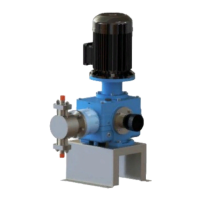
The Encore® 700 metering pump is comprised of a liquid end and a pump
drive mechanism. The stroke length can be varied either manually or with
an optional electric stroke positioner. The pump is driven by an electric
motor that can be coupled either directly to the worm shaft (refer to Dwg.
440.400.001.010A) or indirectly by a pulley drive arrangement (refer to
Dwg. 440.400.001.020A). The pulley drive arrangement provides a wide
range of stroking speeds with the same gear ratio and, therefore, a wide
range of capacities. A double simplex arrangement is also available (refer
to Dwg. 440.400.000.020A).
Pump Drive Mechanism (Refer to Dwg. 440.400.000.010B)
The pump drive mechanism is contained within the gearbox. The motor
rotates the worm wheel through the worm shaft. Worm wheel is coupled
to the variable eccentric non-loss-motion mechanism, which rotates along
with it, converting the rotational motion into the reciprocating motion of
the crosshead (27) through a connecting rod (31). The crosshead provides
a link between the connecting rod and the liquid end. Stroke length of
the pump can be changed from 0 to 100 % by turning the stroke control
knob (47).
Speed Reducer (Refer to Dwgs. 440.400.000.010A)
The pump stroking speed is obtained through gear ratios, which provide
36 spm, 72 spm, and 144 spm. Each stroking speed is available in a pulley
drive configuration or a direct drive configuration. The four-step pulley
combination provides additional stroking speed with each gear ratio.
Stroke Control Mechanism (Refer to Dwg. 440.400.000.010B)
The stroke control mechanism consists of a triangular knob (47) secured
to the bearing carrier (22), which is bolted to the eccentric shaft (45)
and turns on threads through a double row bearing (19) inside the stroke
control housing (25). The stroke control housing has a linear scale show-
ing 0 to 100%. This scale indicates the percent stroke length of the pump.
WT.440.400.001.UA.IM.1012
29