ENCORE
®
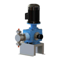
700 METERING PUMP
Disassembly of Complete Pump
WARNING: TO AVOID POSSIBLE SEVERE PERSONAL INJURY OR EQUIP-
MENT DAMAGE, TURN POWER OFF BEFORE SERVICING.
WARNING: TO AVOID POSSIBLE SEVERE PERSONAL INJURY FROM BE-
ING SPRAYED BY LIQUID UNDER PRESSURE, ALLOW SYSTEM TO DRAIN
FULLY BEFORE ATTEMPTING TO DISASSEMBLE PIPING AND REMOVING
VALVES OR HEADS.
The procedures below describe a simplex arrangement with manual
stroke control.
All O-rings must be lightly lubricated with silicone grease before as-
sembly.
Under normal operating conditions, disassembly of the gearbox is not
required. Should disassembly be necessary, proceed as follows:
•
Gearbox Cover Removal (refer to Dwg. 440.400.001.010A or Dwg.
440.400.001.020A)
a.
Remove the liquid end, which includes the valves, head, and
diaphragm, as described paragraph 4.4.2.
b.
For a direct drive, refer to Dwg. 440.400.001.010A. Remove the
electric motor and set aside. Do not remove the coupling flange un-
less it is to be replaced. Remove the motor support (5), loosen the
set screws, and remove the coupling flange. Proceed to step d.
c.
For a pulley drive, refer to Dwg. 440.400.001.020A. Remove the
belt guard (10), loosen the belt (9), and remove the electric motor.
The pulley (2) need not be removed from the motor shaft unless
it is being replaced. Loosen the set screws (8) on the worm shaft
pulley (7) and pull out the pulley.
d.
Unscrew all of the M8 screws that secure the cover (1, Dwg.
440.400.001.010A, or 22, Dwg. 440.400.001.020A) and pry it
open with a suitable screwdriver. The complete mechanism is
now exposed.
NOTE: Two slots are provided for this purpose, one in the front and
one in the back. Silicone RTV is used as a seal and it requires a gentle
tap to break the seal. Note the locations of the special washer and
all the screws.
•
Worm Shaft and Worm Wheel Removal ( refer to Dwg.
440.400.000.010A&B)
WT.440.400.001.UA.IM.1012
42