ENCORE
®
700 METERING PUMP
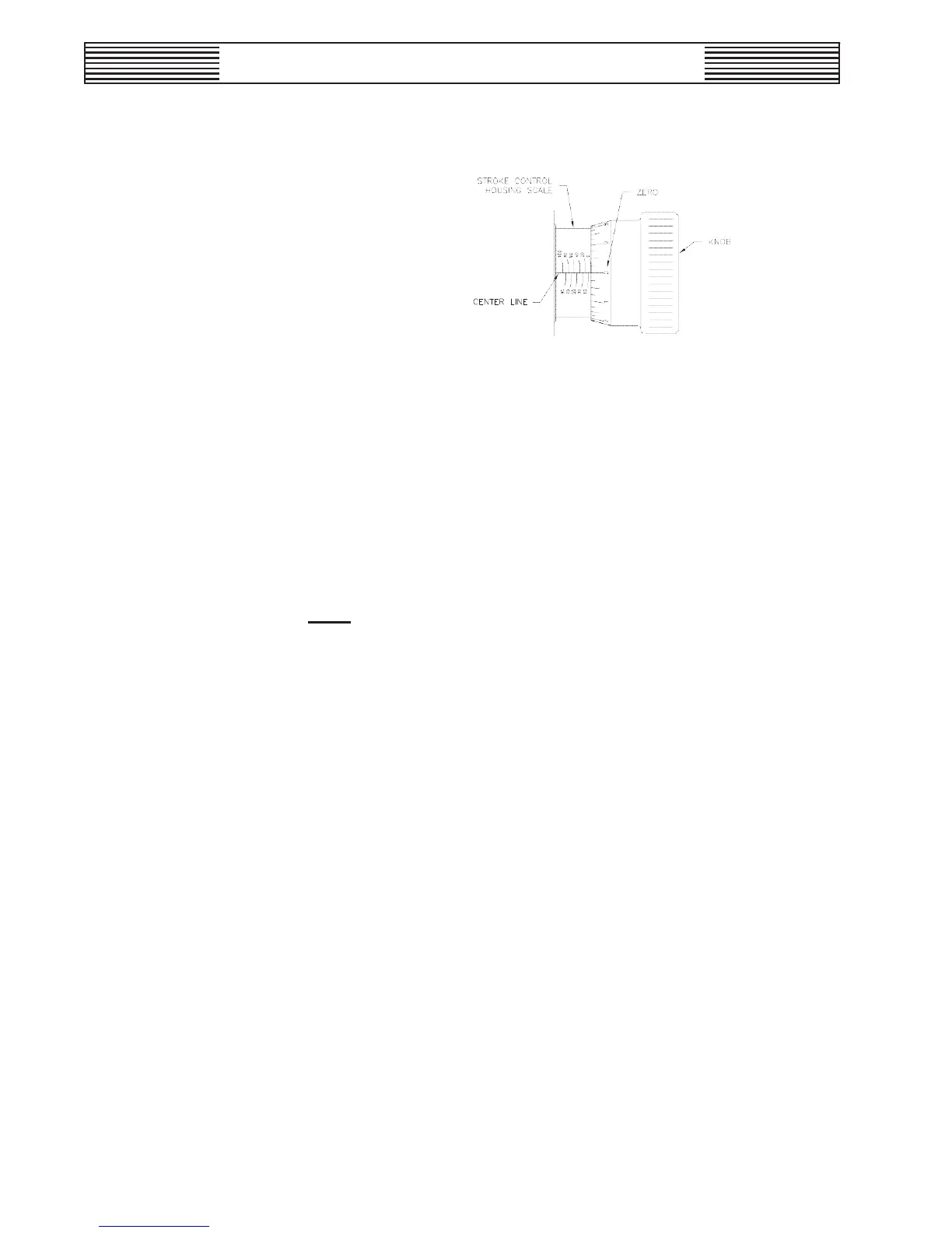
Figure 4-2. Stroke Control Alignment
n.
Push the knob past the O-ring for manual position (quad-ring for
automatic po
sition) until the front edge of the knob is in line with
th
e zero percent line on the stroke control housing scale.
o.
Slide the knob, if necessary, to align the scales as shown in Fig-
ure 4-2. Tighten the three M6 set screws equally. Make sure the
set sc
rews that are used have a Nylok
™
patch on the threads to
prevent o
il leakage.
NOTE: All O-rings must be lightly lubricated with silicone grease
before assembly.
•
Gearbox Cover Installation for Direct Drive (refer to Dwg.
440.400.001.010A)
a.
Position lower taper roller bearing to worm shaft and install to
th
e gearbox.
b.
Install shims and taper roller bearing.
c.
Temporarily install the cover, tightening the four bolts closest to
th
e worm shaft that threads to the gearbox.
d.
Check that end play is within .005". If not, select proper shims.
e.
Remove the cover and apply grease to the top bearing.
f. Apply 1/8" bead of RTV around the top lip of the gearbox.
g.
Install the cover and tighten all bolts.
h.
Install one coupling flange to the worm shaft, tighten the two
set scre
ws.
i.
Mount the motor support and secure with four M8 screws (longer
WT.440.400.001.UA.IM.1012
47