Section 4 Auto-Zone Plus
4-4 Start-Up and Troubleshooting
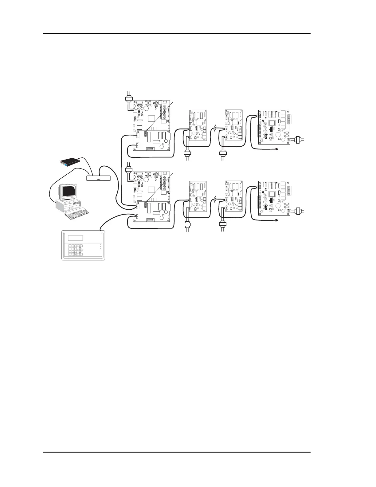
The Network communications loop should only be connected to the MiniLink’s Network
terminals on the Zone Manager(s), and the CommLink II.
All communications wiring should be labeled to avoid confusion and to aid future
servicing.
I15.CDR 10/29/96
LINE
LINE
LINE
LINE
LINE
NETWORK LOOP
WATTMASTERCONTROLS, INC.
COMM LINK II
COMM LINK II
INTERFACE
( MULTIPLE LOOP VERSION )
COMPUTER
(OPTIONAL)
Remote Link
(OPTIONAL)
NET
WORK
LOOP
LOCAL LOOP #1
HVAC UNIT #1
ZONE MANAGER
CLUSTER ADDRESS
SWITCH SET TO 1
RS-485 COMM LOOP
ZONE
CONTROLLER
#1
ZONE
CONTROLLER
#16
CONSTANT VOLUME
CONTROLLER
( IF USED )
COMM
PWR
COMM
PWR
RELAY
OUTPUT
COM
1-3
OUT
OUT
1
2
COM
4-5
OUT
OUT
OUT
3
4
5
24VAC
GND
PWR
COMM
T
SHLD
LD4
REC.
12V
AIN
1
2
3
4
5
GND
GND
AOUT
AIN
AIN
AIN
AIN
4-5
OUT
COMM
TEST
32K
8K
RAM EPROM
ADDRESS ADD
PRESSURE
SENSOR
485
COMM
R
YS101564
EWDOG
0-5
VDC
0-1
VDC
TO ANY ADDITIONAL
CV CONTROLLER OR
ADD ON DEVICES
NET
WORK
LOOP
LOCAL LOOP #2
HVAC UNIT #2
ZONE MANAGER
CLUSTER ADDRESS
SWITCH SET TO 2
ZONE
CONTROLLER
#1
ZONE
CONTROLLER
#16
CONSTANT VOLUME
CONTROLLER
( IF USED )
COMM
PWR
COMM
PWR
RELAY
OUTPUT
COM
1-3
OUT
OUT
1
2
COM
4-5
OUT
OUT
OUT
3
4
5
24VAC
GND
PWR
COMM
T
SHLD
LD4
REC.
12V
AIN
1
2
3
4
5
GND
GND
AOUT
AIN
AIN
AIN
AIN
4-5
OUT
COMM
TEST
32K
8K
RAM EPROM
ADDRESS ADD
PRESSURE
SENSOR
485
COMM
R
YS101564
EWDOG
0-5
VDC
0-1
VDC
TO ANY ADDITIONAL
CV CONTROLLERS OR
ADDONUNITS
ADDRESS=17
ADDRESS=17
WATTMASTER CONTROLS INC.WATTMASTERCONTROLS INC.
Override
CommunicationCommunication
Alarm
98
7
CLEAR
0
DEC. MINUS
ENTER
NO ALARM(S)NO ALARM(S)
06/11/96 03:38PM FRI06/11/96
03:38PM FRI
AUTOZONE COOL MODEAUTOZONE
COOL MODE
2
5
4
1
6
3
OCCUPIED
MENU ESCESC
SYSTEMMANAGER
SYSTEM MANAGER
Line
Line
Figure 4-2: Communications Loop Routing
1.2.1 Communications Checklist
• All Zone Managers are set to address 17
• Each Local loop has a unique cluster address
• Zone Controllers are addressed from 1 to 16
• CV Units are addressed from 18 to 30
• Power has been cycled after changing addresses
• A CommLink II is powered and connected to the Network loop
• Be sure Local loops are not connected to each other
• System Manager is connected to a Local loop, not the network loop