Auto-Zone Plus Section 4
Start-Up and Troubleshooting 4-19
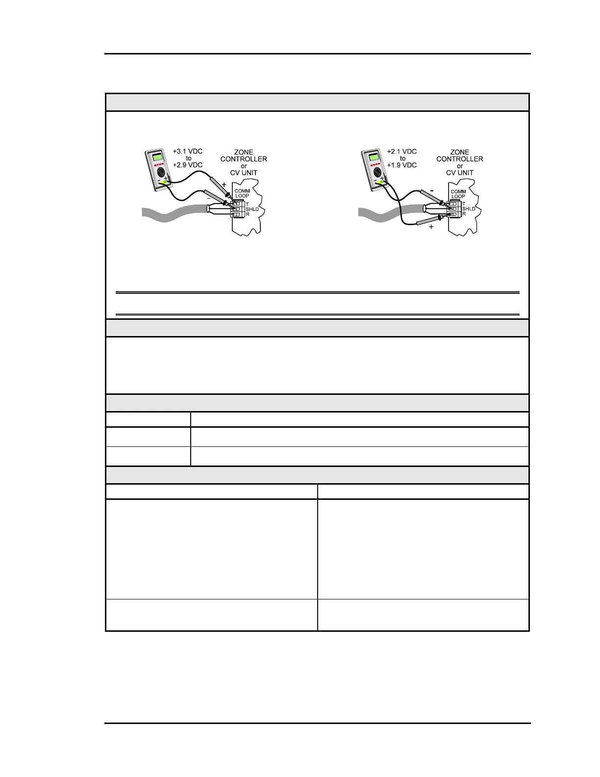
1.3.9 Checking the Local Loop at a Controller
Diagram
Meter Set To Read DC Volts
The indicated readings are typical of a normal operating system. Actual readings may vary
slightly due to the number of units installed and other factors. Any significant deviation
from these values generally indicates a problem.
Note These tests assume that a zone manager is connected and powered up.
Overvie
Proper loop voltages are essential for reliable communications. It is normal to see
fluctuations on an operating communications loop. The average value should be close to the
acceptable range described below. Values will vary upon initial powerup for about 30-45
seconds. The voltages may fluctuate as normal communications occur.
Measurements
Local Loop Acceptable Range
T - SHLD 2.9 - 3.1 Volts DC
R - SHLD 1.9 - 2.1 Volts DC
Action
Condition Action
If meter reads between 2.4 VDC and 2.5
VDC
The Comm Loop “floats” at 2.4 - 2.5VDC
when only controllers are connected to the
loop. When a Zone Manager is connected it
will “bias” each side of the loop to the
values listed above.
1) No CommLink II or Zone Manager is
connected and powered up.
2) If a CommLink II or Zone Manager is
connected look for “open” wiring.
If voltages are too high or too low on either
side
One or more devices connected to this loop
have damaged Comm Driver chips.