OPERATING INSTRUCTIONS
Model
2001
REMOTE
PLUG
Id
[SWEEP WIDTH
CONTROL CIRCUIT
FRONT PANEL
SWEEP WIDTH
CONTROL
To provide
FM
modulation, connect as shown at right and
set the Front Panel MODE Switch for CW operation.
TO
EXTERNAL
MODULATING
SOURCE
PERCENT
MODULATION
CONTROL
T
LSWEEP
WIDTH
4
I
CONTROL
CIRCUIT
FRONT
PANEL
SWEEP
WIDTH
CONTROL
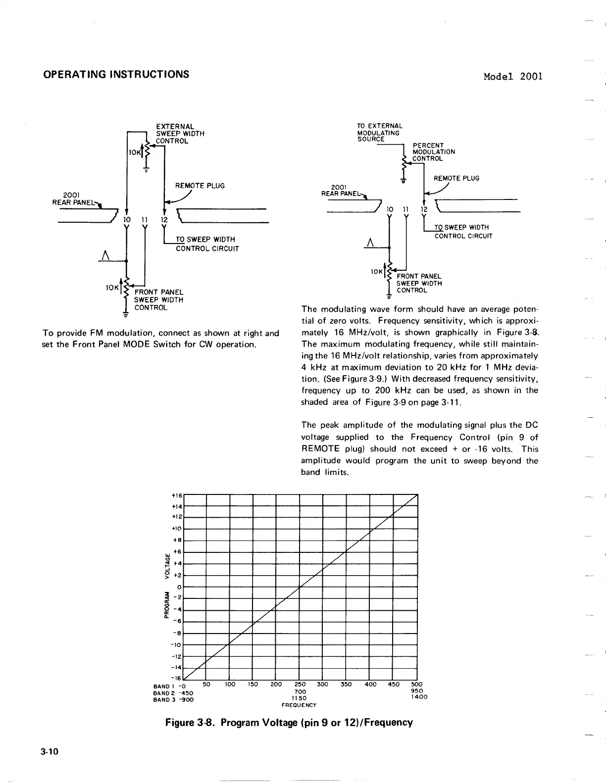
The modulating wave form should have an average poten-
tial of zero volts. Frequency sensitivity, which is approxi-
mately
16
MHzIvolt, is shown graphically in Figure 3-8.
The maximum modulating frequency, while still maintain-
ing the
16
MHzIvolt relationship, varies from approximately
4
kHz at maximum deviation to 20 kHz for
1
MHz devia-
tion. (See Figure
3-9.) With decreased frequency sensitivity,
frequency up to 200 kHz can be used, as shown in the
shaded area of Figure 3-9 on page 3-1
1.
The peak amplitude of the modulating signal plus the DC
voltage supplied to the Frequency Control (pin 9 of
REMOTE plug) should not exceed
+
or
-16
volts. This
amplitude would
program the unit to sweep beyond the
band limits.
Figure
38.
Program Voltage (pin
9
or 12)lFrequency
OPERATING INSTRUCTIONS
2001
REAR PANEL
...
___
---JJ
10
=
11
EXTERNAL
SWEEP WIDTH
CONTROL
REMOTE
PLUG
12
\\....
_____
_
~
SWEEP WIDTH
CONTROL
CIRCUIT
FRONT
PANEL
SWEEP WIDTH
CONTROL
2001
TO
EXTERNAL
MODULATING
SOURCE
PERCENT
MODULATION
CONTROL
REMOTE
PLUG
Model 2001
REAR
PANEL)l
___
~J
10
11
1\
12
\1....
_____
_
~
SWEEP
WIDTH
CONTROL CIRCUIT
J
lOKt
FRONT PANEL
SWEEP
WIDTH
CONTROL
=
To
provide FM
modulation,
connect
as
shown at
right
and
set
the
Front
Panel
MODE
Switch
for
CW
operation.
The
modulating
wave
form
should have
an
average poten-
tial
of
zero volts. Frequency sensitivity,
which
is
approxi-
mately
16
MHz/volt,
is
shown graphically in Figure 3-8.
The
maximum
modulating
frequency,
while
still
maintain-
ingthe
16
MHz/volt
relationship, varies
from
approximately
4
kHz
at
maximum
deviation
to
20
kHz
for
1
MHz
devia-
tion.
(See
Figure 3-9.)
With
decreased frequency sensitivity,
frequency
up
to
200
kHz
can be used,
as
shown in
the
shaded
area
of
Figure 3-9
on
page
3-11.
3-10
6
+1
+14
+12
+10
+8
+6
'"
C>
;'!
+4
..J
~
+2
o
~
-2
II:
~
-4
Q.
-6
-8
-10
-12
-14
-16
V
8AND 1
-0
BAND 2
-450
BAND 3
-900
./
/
/
./
50
100
150
/
V
The peak
amplitude
of
the
modulating
signal plus
the
DC
voltage supplied
to
the Frequency
Control
(pin 9
of
REMOTE
plug) should
not
exceed +
or
-16 volts.
This
amplitude
would
program
the
unit
to
sweep
beyond
the
band
limits.
/
V
./
/
/
/
/'
./
200
250
300
700
350
400
450
500
950
1400
1150
FREQUENCY
Figure 3-8. Program Voltage (pin 9 or 12)/Frequency