MAINTENANCE
Model
2001
WITH NO INPUT, ADJUST HORIZONTAL POSITION
TO
SET
THE
DO^
AT
THE
5~rn
ICENTERI
LINE
monic markers on the scope display. Residual FM can be
read directly on the scope display by noting the amount of
ADJUST
HORIZONTAL
SENSITIVITY
iitter of the marker. (A iitter of
0.2cm
would be equal to
I
FOR A DISPLAY WlDTH OF EXACTLY
+
5.2
crn
.
.
20 kHz).
Change SWEEP TIME selector from LlNE to the 0.1
-
0.01
position and again read the marker jitter. The additional
jitter in this position represents the line related residual.
Maximum allowable jitter is 15 kHz. Alternate Method to
read residual FM is with a spectrum analyzer.
5.3.5 FREQUENCY DRIFT
Return SWEEP
TIME selector to LlNE and again calibrate
the display's sweep width to 1 MHz. Position the marker to
the exact center of the oscilloscope display and read fre-
quency drift directly from the scope display by noting the
change in the markers position with time. Each centimeter
represents 100 kHz. When reading drift over long periods of
time, calibrate the display sweep width to 5 MHz, using the
I
BAND 1
0
I
250
I
500
BAND
2
450
700
950
BAND
3
900
1150
1400
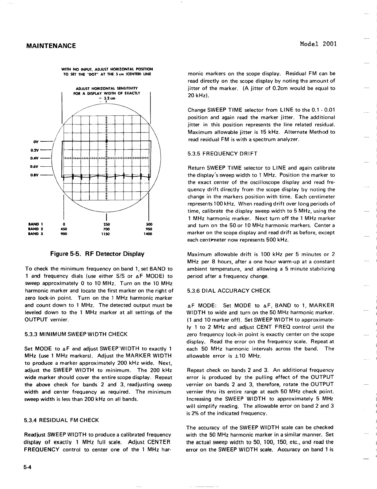
Figure
5-5.
RF Detector Display
To check the minimum frequency on band 1, set BAND to
1 and frequency dials (use either
SIS or AF MODE) to
sweep approximately
0 to 10 MHz. Turn on the 10 MHz
harmonic marker and locate the first marker on the right of
zero lock-in point. Turn on the 1 MHz harmonic marker
and count down to 1 MHz.
The detected output must be
leveled down to the 1 MHz marker at all settings of the
OUTPUT vernier.
5.3.3 MINIMUM SWEEP
WI DTH CHECK
Set MODE to
AF and adjust SWEEP'WIDTH to exactly
1
MHz (use 1 MHz markers). Adjust the MARKER WIDTH
to produce a marker approximately 200 kHz wide. Next,
adjust the SWEEP WIDTH to minimum. The 200 kHz
wide marker should cover the entire scope display. Repeat
the above check for bands
2
and 3, readjusting sweep
width and center frequency as required. The minimum
sweep width is less than 200 kHz on all bands.
5.3.4 RESIDUAL FM CHECK
Readjust SWEEP WIDTH to produce a calibrated frequency
display
of
exactly
1
MHz
full scale. Adjust
CENTER
FREQUENCY control to center one of the 1 MHz har-
1 MHz harmonic marker. Next turn off the
1
MHz marker
and turn on the 50 or 10 MHz harmonic markers. Center a
marker on the scope display and read drift as before, except
each centimeter now represents 500 kHz.
Maximum allowable drift is 100 kHz per 5 minutes or 2
MHz per
8
hours, after a one hour warm-up at a constant
ambient temperature, and allowing a 5 minute stabilizing
period after a frequency change.
5.3.6
DIAL ACCURACY CHECK
AF MODE: Set MODE to AF, BAND to 1, MARKER
WIDTH to wide and turn on the 50 MHz harmonic marker.
(1 and 10 marker off). Set SWEEP WIDTH to approximate-
ly 1 to 2 MHz and adjust CENT FREQ control until the
zero frequency lock-in point is exactly center on the scope
display. Read the error on the frequency scale. Repeat at
each 50 MHz harmonic intervals across the band. The
allowable error is
210 MHz.
Repeat check on bands 2 and 3. An additional frequency
error is produced by the pulling effect of the OUTPUT
vernier on bands
2
and 3, therefore, rotate the OUTPUT
vernier thru its entire range at each 50 MHz check point.
Increasing the SWEEP WIDTH to approximately 5 MHz
will simplify reading. The allowable error on band 2 and 3
is
2%
of the indicated frequency.
The accuracy of the SWEEP WIDTH scale can be checked
with the 50 MHz harmonic marker in a similar manner. Set
the actual sweep width to 50, 100, 150, etc., and read the
error on the SWEEP WIDTH scale. Accuracy on band 1 is
MAINTENANCE
WITH
NO
INPUT,
ADJUST
HORIZONTAL
POSITION
TO
SET
THE
-'DOT"
AT
THE
5
em
(CENTERI
LINE
ADJUST
HORIZONTAL
SENSITIVITY
FOR
A
DISPLAY
WIDTH
OF
EXACTLY
+
5.2em
- I
//"'"
/'
~.L_
~
/
ov
O.2V
-I
I
--
O.4V
--
-
O.6V
O.IV
-\~
BAND
I
lAND
2
BAND
3
I""
o
450
900
~
I
250
700
1150
-
~
i"'"
V
/
500
950
1400
Figure 5-5. R F Detector Display
To
check
the
minimum
frequency on band
1,
set
BAND
to
1 and frequency dials (use either SIS
or
~
F MODE)
to
sweep
approximately
0
to
10
MHz.
Turn
on the 10
MHz
harmonic
marker and locate the
first
marker
on
the
right
of
zero
lock-in
point.
Turn
on the 1
MHz
harmonic
marker
and
count
down
to
1 MHz. The detected
output
must
be
leveled
down
to
the 1
MHz
marker
at
a"
settings
of
the
OUTPUT
vernier.
5.3.3
MINIMUM
SWEEP
WIDTH
CHECK
Set
MODE
to
~F
and adjust
SWEEP'WIDTH
to
exactly 1
MHz
(use 1
MHz
markers).
Adjust
the
MARKER
WIDTH
to
produce a
marker
approximately
200
kHz
wide.
Next,
adjust the SWEEP
WIDTH
to
minimum.
The
200
kHz
wide
marker
should cover the entire scope display. Repeat
the above check
for
bands 2 and 3, readjusting sweep
width
and center frequency
as
required.
The
minimum
sweep
width
is
less
than
200
kHz
on
a"
bands.
5.3.4
RESIDUAL
FM
CHECK
Readjust SWEEP
WIDTH
to
produce a calibrated frequency
display
of
exactly
1
MHz
full
scale.
Adjust
CENTER
FREQUENCY
control
to
center one
of
the 1
MHz
har-
5-4
Model 2001
monic
markers on the scope display. Residual FM can
be
read
directly
on
the scope display
by
noting
the
amount
of
jitter
of
the marker.
(A
jitter
of
0.2cm
would
be
equal
to
20
kHz).
Change SWEEP
TIME
selector
from
LINE
to
the
0.1 - 0.01
position
and again read the marker
jitter.
The
additional
jitter
in this
position
represents the line related residual.
Maximum
allowable
jitter
is
15
kHz.
Alternate
Method
to
read
residual FM
is
with
a spectrum analyzer.
5.3.5
FREQUENCY
DRIFT
Return SWEEP
TIME
selector
to
LINE
and again calibrate
the display's sweep
width
to
1 MHz. Position the marker
to
the
exact
center
of
the oscilloscope display and read fre-
quency
drift
directly
from
the scope display
by
noting
the
change in the markers
position
with
time. Each centimeter
represents 100 kHz. When reading
drift
over long periods
of
time,
calibrate the display sweep
width
to
5
MHz,
using the
1
MHz
harmonic
marker.
Next
turn
off
the 1
MHz
marker
and
turn
on the
50
or
10
MHz
harmonic
markers. Center a
marker on the scope display and read
drift
as
before, except
each
centimeter
now
represents
500
kHz.
Maximum
a"owable
drift
is
1
00
kHz per 5 minutes
or
2
MHz
per 8 hours,
after
a one
hour
warm-up
at
a constant
ambient
temperature, and
allowing
a 5
minute
stabilizing
period
after
a frequency change.
5.3.6
DIAL
ACCURACY
CHECK
~F
MODE:
Set
MODE
to
~F,
BAND
to
1,
MARKER
WIDTH
to
wide
and
turn
on the 50
MHz
harmonic
marker.
(1
and 10 marker
off).
Set SWEEP
WI
DTH
to
approximate-
ly
1
to
2
MHz
and adjust
CENT
FREQ
control
until
the
zero frequency lock-in
point
is
exactly center on the scope
display.
Read
the
error
on the frequency scale. Repeat at
each 50
MHz
harmonic
intervals across the band. The
a"owable
error
is
± 10 MHz.
Repeat check on bands 2 and 3.
An
additional
frequency
error
is
produced
by
the
pulling
effect
of
the
OUTPUT
vernier on bands 2 and 3, therefore,
rotate
the
OUTPUT
vernier
thru
its
entire range
at
each
50
MHz
check
point.
Increasing the SWEEP
WIDTH
to
approximately
5 MHz
will
simplify
reading. The
a"owable
error on band 2 and 3
is
2%
of
the ind icated frequency.
The
accuracy
of
the SWEEP
WIDTH
scale
can be checked
with
the 50
MHz
harmonic marker in a similar manner. Set
the actual sweep
width
to
50, 100, 150, etc., and
read
the
error
on the SWEEP
WI
DTH
scale. Accuracy on band 1
is
 Loading...


