GENERAL INFORMATION
TABLE
1-1.
Specifications (Con't.)
Model
2001
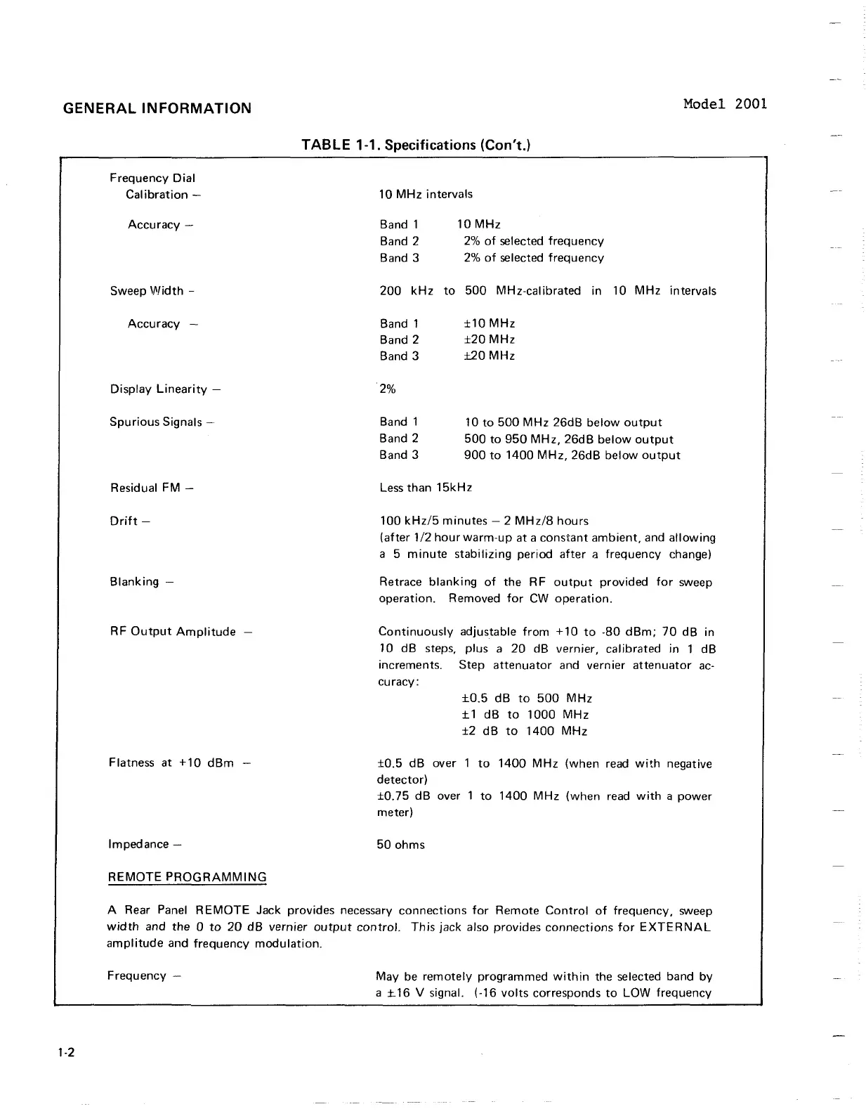
Frequency Dial
Calibration
-
Accuracy
-
10
MHz intervals
Band
1 10
MHz
Band
2
2%
of selected frequency
Band
3
2%
of selected frequency
Sweep Width
-
200
kHz to
500
MHz-calibrated in
10
MHz intervals
Accuracy
-
Band 1
f 10
MHz
Band
2 f20
MHz
Band
3
k20
MHz
Display Linearity
-
2%
Spurious Signals
-
Band 1
10
to
500
MHz 26dB below output
Band
2
500
to
950
MHz, 26dB below output
Band
3
900
to
1400
MHz, 26dB below output
Residual FM
-
Less than 15kHz
Drift
-
Blanking
-
RF Output Amplitude
-
Flatness at
+10
dBm
-
100
kHz15 minutes
-
2
MHz18 hours
(after
112
hourwarm-up at a constant ambient, and allowing
a
5
minute stabilizing period after
a
frequency change)
Retrace blanking of the RF output provided for sweep
operation. Removed for CW operation.
Continuously adjustable from
+10
to
-80
dBm;
70
dB in
10
dB steps, plus a
20
dB vernier, calibrated in
1
dB
increments. Step attenuator and vernier attenuator ac-
curacy
:
k0.5
dB to
500
MHz
k1
dB to
1000
MHz
f2
dB to
1400
MHz
f0.5
dB over
1
to
1400
MHz (when read with negative
detector)
f0.75
dB over
1
to
1400
MHz (when read with a power
meter)
Impedance
-
50
ohms
REMOTE PROGRAMMING
A Rear Panel REMOTE Jack provides necessary connections for Remote Control of frequency, sweep
width and the
0
to
20
dB vernier output control. This jack also provides connections for EXTERNAL
amplitude and frequency modulation.
Frequency
-
May be remotely programmed within the selected band by
a
k16
V
signal. (-16 volts corresponds to LOW frequency
GENERAL
INFORMATION
Model
2001
1-2
Frequency
Dial
Calibration
-
Accuracy
-
Sweep IJlJidth -
Accuracy
-
Display
Linearity
-
Spurious
Signals -
Residual FM -
Drift
-
Blanking
-
RF
Output
Amplitude
-
Flatness at
+10
dBm
-
Impedance -
REMOTE
PROGRAMMING
TABLE 1-1. Specifications (Con't.)
10
MHz
intervals
Band 1
Band 2
Band 3
10
MHz
2%
of
selected
frequency
2%
of
selected
frequency
200
kHz
to
500
MHz-calibrated in 10
MHz
intervals
Band 1
Band 2
Band
3
2%
Band 1
Band 2
Band
3
±10
MHz
±20
MHz
±20
MHz
10
to
500
MHz
26dB
below
output
500
to
950
MHz,
26dB
below
output
900
to
1400
MHz,
26dB
below
output
less
than
15kHz
100
kHz/5
minutes
- 2
MHz/8
hours
(after
1/2
hour
warm-up
at a
constant
ambient,
and
allowing
a 5
minute
stabilizing
period
after
a
frequency
change)
Retrace
blanking
of
the RF
output
provided
for
sweep
operation.
Removed
for
CW
operation.
Continuously
adjustable
from
+10
to
-80
dBm;
70
dB
in
10
dB
steps,
plus
a
20
dB vernier, calibrated in 1
dB
increments. Step
attenuator
and vern ier
attenuator
ac-
curacy:
±0.5
dB
to
500
MHz
± 1
dB
to
1000
MHz
±2
dB
to
1400
MHz
±0.5
dB
over 1
to
1400
MHz
(when read
with
negative
detector)
±0.75
dB
over 1
to
1400
MHz
(when
read
with
a
power
meter)
50
ohms
A Rear Panel
REMOTE
Jack provides necessary
connections
for
Remote
Control
of
frequency,
sweep
width
and the 0
to
20
dB
vernier
output
control.
This
jack
also provides
connections
for
EXTERNAL
amplitude
and
frequency
modulation.
Frequency
-
May be
remotely
programmed
within
the selected band
by
a ± 16 V signal. (-16
volts
corresponds
to
LOW
frequency