Thermo Pro 90 2 General description
202
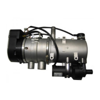
2.1 Combustion air fan
The combustion air fan feeds the air required for combus-
tion to the burner unit.
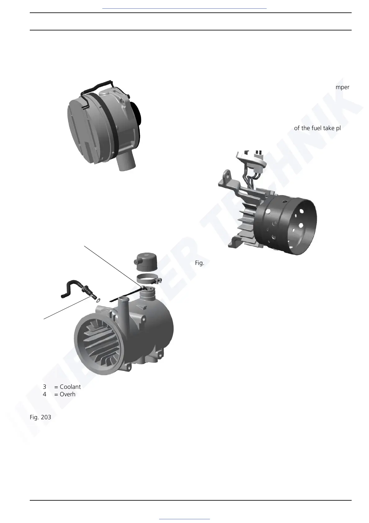
2.2 Heat exchanger
The heat generated in the heat exchanger by combustion is
transferred to the coolant circuit.
2.2.1 Coolant temperature sensor
The coolant temperature sensor detects the coolant temper-
ature at the coolant outlet of the heater as an electrical
resistance. This signal is fed to the control unit, where it is
processed.
2.2.2 Overheating protection
The overheating protection (bi-metal) protects the heater
against impermissibly high operating temperatures. The
overheating protection reacts at a heat transfer temperature
above 127 ± 7 °C and switches off the heater.
The overheating protection is reset automatically at temper-
atures below 65 ± 5 °C.
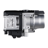
2.3 Burner unit
The evaporation and pre-combustion of the fuel take place
in the burner unit.
2.3.1 Glow plug
The fuel-air mixture is ignited with the glow plug when the
heater is started. The glow plug is positioned axially in the
centre of the burner unit.
Fig. 202 Combustion air fan
Fig. 203 Heat exchanger
4
3
3 = Coolant temperature sensor
4 = Overheating protection
Fig. 204 Burner unit