5 Faults, Troubleshooting Thermo Pro 90
503
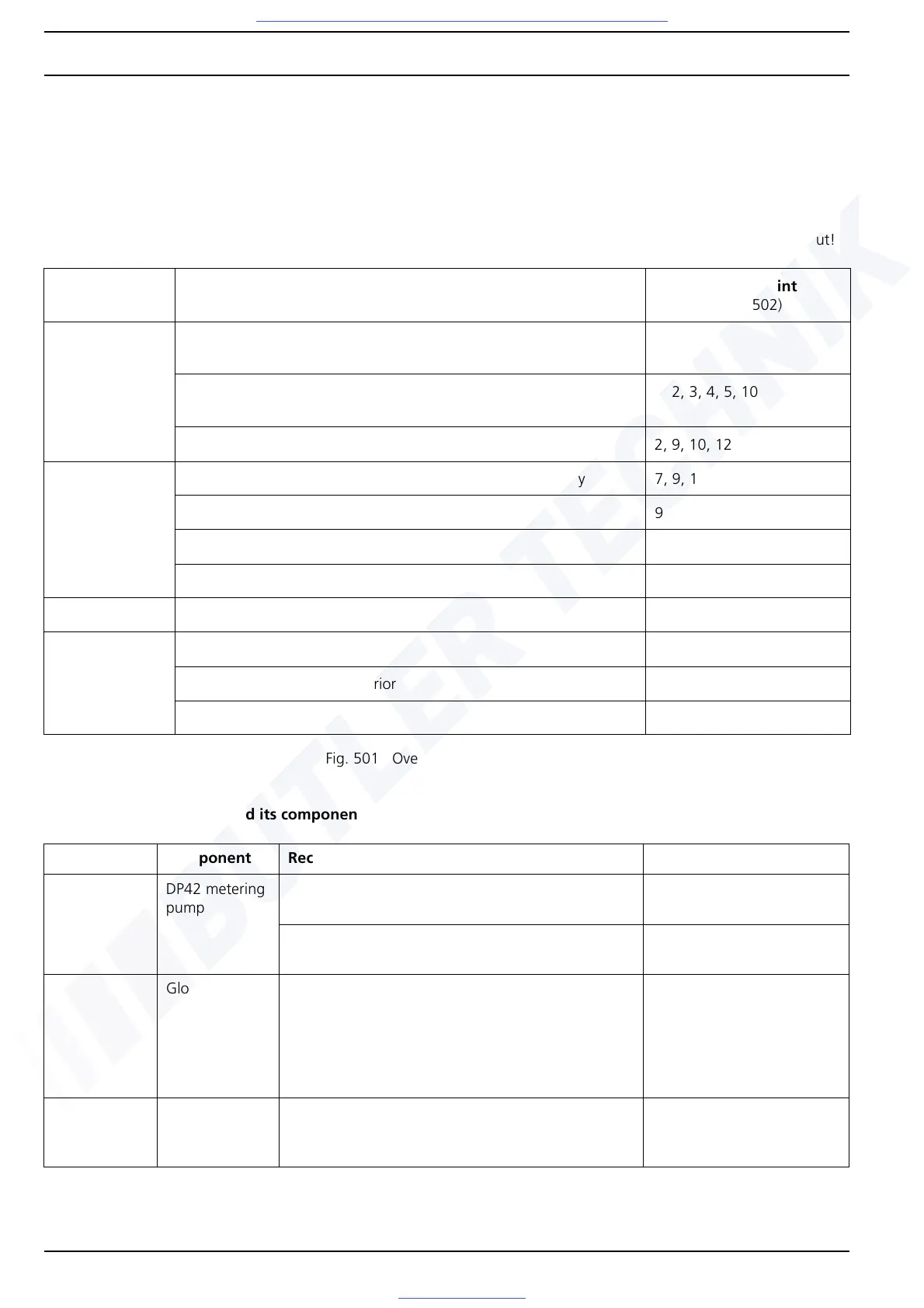
5.1 Troubleshooting without error code output
Possible faults
The overview only shows some of the possible faults. The Webasto Service Hotline must be contacted in individual cases.
IMPORTANT
The error points specified from Tables Fig. 501 and Fig. 502 DO NOT match the error code numbers for error code output!
Functional test of heater and its components
Heater Mode Fault Description Possible error point
(see Table Fig. 502)
Start Heater does not react, no component starts up, no display by opera-
tion indicator
6, 8
Heater does not start, short start-up, then changes into run-on imme-
diately, operation indicator flashes (error code output)
1, 2, 3, 4, 5, 10
Heater smokes in start-up phase 2, 9, 10, 12, 15, 19
Combustion
operation
Heater runs through start, however switches off prematurely 7, 9, 10, 12, 13, 15, 19, 20
Heater has rough combustion 9, 12, 19
Heater smokes in heating phase 9, 12, 15, 19, 21
Heater runs, vehicle interior cold 17
Run-on Heater smokes in run-on phase 15, 19
Other Fuel odour 1, 2, 12
Exhaust odour in vehicle interior 16
Coolant loss 11, 14
Fig. 501 Overview of possible faults
Error point Component Recommended workshop action Parameter
1 DP42 metering
pump
Check continuity and seating of flat spring contacts
of metering pump line
Measure cold resistance of DP42 metering pump at
25 °C, also see Section 6.4.5
4.95 to 5.45 ohms, Test
current: < 1 mA
2 Glow plug Measure glow-plug resistance value on glow plug
connector X2, also see Section 6.4.2
Cold resistance at 25 °C:
– 0.235 to 0.305 ohms for
the 12 V variant
– 0.670 to 0.870 ohms for
the 24 V variant ("green"
marking on glow plug)
3 Coolant tem-
perature sensor
For information on checking the cold resistance of
the coolant temperature sensor, also see Section
6.4.1
At 25 °C:
990 to 1,010 ohms, Test
current: < 1 mA
Fig. 502 Overview of functional test of heater and its components