7 Circuit diagrams Thermo Pro 90
701
7 Circuit diagrams
Fig. 703 shows the circuit of the Thermo Pro 90 heater, parking heater with standard timer without ADR.
Fig. 704 shows the circuit of the Thermo Pro 90 heater, parking heater with On/Off switch without ADR.
Fig. 705 shows the circuit of the Thermo Pro 90 heater, parking heater with On/Off switch with ADR with auxiliary drive.
Fig. 706 shows the circuit of the Thermo Pro 90 heater, parking heater with On/Off switch with ADR without auxiliary drive.
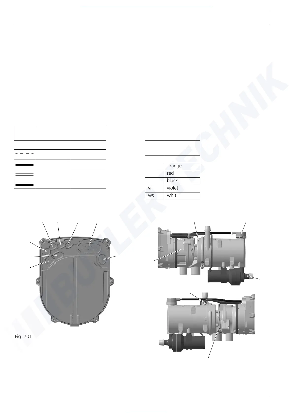
For connector assignment on control unit, see Fig. 701.
For positioning of electrical components on heater, see Fig. 702.
For the legend for wiring diagrams, see Table 1, Table 2 and Table 3.
Table 1 Cable cross-sections
Length
<7.5m
Length
7.5 to 15 m
0.75 mm
2
1.0 mm
2
1.0 mm
2
1.5 mm
2
1.5 mm
2
2.5 mm
2
2.5 mm
2
4.0 mm
2
4.0 mm
2
6.0 mm
2
Table 2 Cable colours
bl blue
br brown
ge yellow
gn green
gr grey
or orange
rt red
sw black
vi violet
ws white
Fig. 701 Connector assignment on control unit
X1
X6
X4 X7 X8
X3
X2
X5
Fig. 702 Positioning of electrical components on heater
UP
ÜHS
BM
GS
WTS
ATS