9 Maintaining and Replacing Components Thermo Pro 90
905
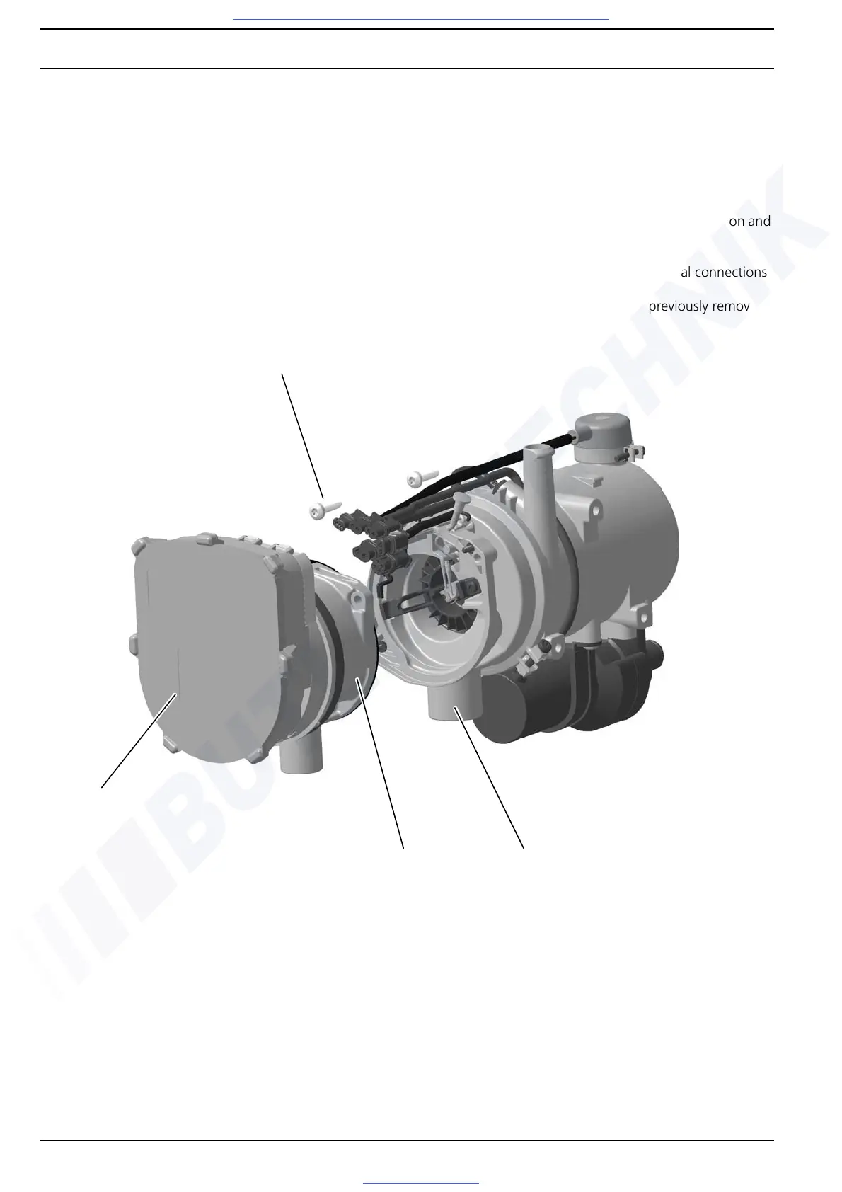
9.7 Replacing combustion air fan
Removal
1. Remove heater (see Section 8.5.1), depending on space
required.
2. Disconnect electrical connections (see Section 9.3).
3. Remove screws (2, Fig. 903). Pull off control unit if nec-
essary.
4. Pull combustion air fan (1) off burner head (4) and
remove.
5. Carry out measures on components when dismantled
(see Section 9.2).
Installation
NOTE
Ensure intact, moulded-on sealing bead.
1. Position combustion air fan (1) in assembly position and
fasten with screws (2).
2. Tighten screws (2) to 3 Nm ± 10%.
3. Mount control unit and connect electrical connections
(see Section 9.3).
4. Install heater (see Section 8.5.2) if previously removed.
Fig. 903 Replacing combustion air fan
2
4
1
3
1 = Combustion air fan
2 = Screw (2x)
3 = Control unit
4 = Burner head