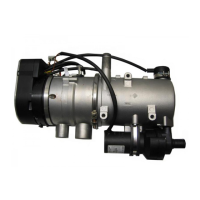
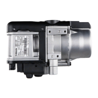
9 Maintaining and Replacing Components Thermo Pro 90
907
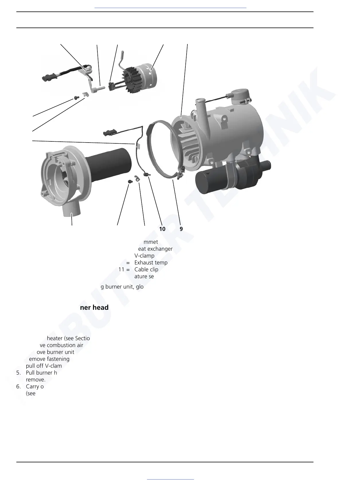
Fig. 904 Replacing burner unit, glow plug, burner head and exhaust temperature sensor
9.9 Replacing burner head
Removal
1. Remove heater (see Section 8.5.1).
2. Remove combustion air fan (see Section 9.7).
3. Remove burner unit with glow plug (see Section 9.8).
4. Remove fastening screw of V-clamp (9, Fig. 904) and
pull off V-clamp.
5. Pull burner head (2) out of heat exchanger (8) and
remove.
6. Carry out measures on components when dismantled
(see Section 9.2).
NOTE
When replacing the burner head, the exhaust temperature
sensor must be removed from the old burner head and
installed in the new burner head. See Section 9.12.
Installation
NOTE
The burner head or the exhaust outlet connection can still
be aligned when installing it in the vehicle.
1. Guide burner head (2, Fig. 904) into heat exchanger (8),
align if necessary and fasten with V-clamp (9).
2. Tighten fastening screw of V-clamp to 3 Nm ± 10% if
necessary.
3. Install burner unit with glow plug (see Section 9.8).
4. Mount combustion air fan (see Section 9.7).
5. Install heater (see Section 8.5.2).
7
1 = Burner unit
2 = Burner head
3= Screw
4 = Glow plug
5 = Hold-down device
6= Screw
7= Grommet
8 = Heat exchanger
9= V-clamp
10 = Exhaust temperature sensor
11 = Cable clip for exhaust temper-
ature sensor
12 = Hold-down device for exhaust
temperature sensor
13 = Screw for exhaust temperature
sensor
4
1
5
8
10
2
6
3
912
13
11