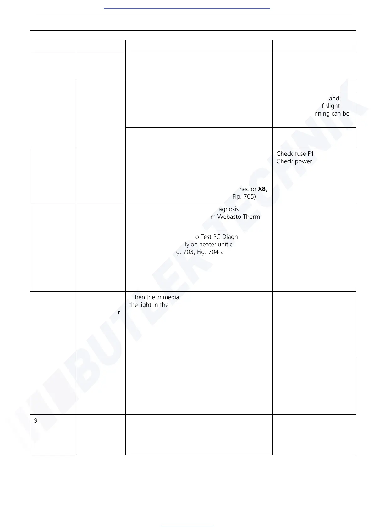
Thermo Pro 90 5 Faults, Troubleshooting
504
4 Combustion air
fan
Combustion air fan short circuit/open circuit
Check fan wiring and replace component if neces-
sary
5 U4840 circula-
tion pump
Check wiring
Conduct component test to check function of circu-
lation pump with Webasto Thermo Test PC Diagno-
sis.
Touch pump with hand;
pump functions if slight
vibration or running can be
felt
Check self-bleeding installation position, also see
Section 8.5.2
6 Power supply With Webasto Thermo Test PC Diagnosis
Measure operating voltage from Webasto Thermo
Test PC Diagnosis
Check fuse F1
Check power supply
Without Webasto Thermo Test PC Diagnosis
Measure power supply on heater unit connector X8,
Pin 12 (also see Fig. 703, Fig. 704 and Fig. 705)
7 Undervoltage
detection
With Webasto Thermo Test PC Diagnosis
Measure operating voltage from Webasto Thermo
Test PC Diagnosis
– 12 V variant:
The voltage may not
drop below 10.5 V for
more than 10
consecutive seconds
– 24 V variant:
The voltage may not
drop below 20.0 V for
more than 10
consecutive seconds
– Check fuse F1
Without Webasto Thermo Test PC Diagnosis
Measure power supply on heater unit connector X8,
Pin 12 (also see Fig. 703, Fig. 704 and Fig. 705)
8 Operation indi-
cator
(standard timer
or ON/OFF
switch)
When the immediate heat button/switch is operated,
the light in the display/switch is activated
Operation indicator of
standard timer:
– Measure power supply
on connector X9, Pin 11
– Check continuity on
connector X9, Pin 12 to
earth
– Check fuse F2
Operation indicator of
switch:
– Measure power supply
on switch S4, Pin A
– Check continuity on
switch S4, Pin F to earth
– Check fuse F2
9 DP42 metering
pump
Measure fuel feed rate (use Webasto Thermo Test PC
Diagnosis for controlling the metering pump), also
see Section 6.4.5
Diesel feed rate at metering
pump frequency of 9 Hz and
feed time of 180 s:
49.5 to 54.7 ml
Check fuel line connection to DP42 metering pump
Error point Component Recommended workshop action Parameter
Fig. 502 Overview of functional test of heater and its components