2 General description Thermo Top Evo
202
2.1 Combustion-air fan unit/control unit
The combustion-air fan unit contains:
• the heater type label
• the connection piece for the combustion air pipe
• the control unit with the plug-in contacts
• the engine and the impeller
The combustion air fan supplies the air required for the
combustion process from the combustion air inlet to the
combustion chamber.
NOTE
It is not permissible to dismantle the combustion-air fan
unit.
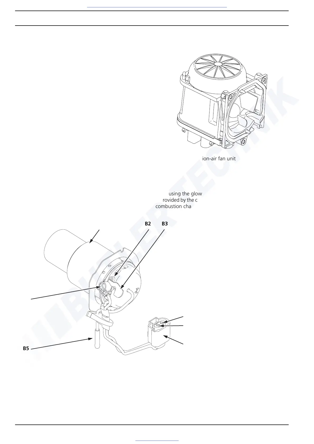
2.2 Burner unit
The fuel-air mixture is processed and the actual combustion
takes place in the burner unit. The fuel flows via the fuel
pipe to the evaporator, is distributed there and is evapo-
rated using the glow plug. The air required for combustion
is provided by the combustion-air fan unit and flows into the
combustion chamber via holes in the burner.
Fig. 202 Combustion-air fan unit
Fig. 203 Burner unit
B1
B1 = Combustion pipe
with evaporator
mount and evapora-
tor
B2 = Retaining spring for
glow plug
B3 = Cooling flag for glow
plug
B4 = Glow plug/Flame
monitor
B5 = Fuel pipe
B9 = Connector for glow
plug/flame monitor
B4
B2 B3
B5
B9
Pin 1
Pin 2

 Loading...


