9 Repair Thermo Top Evo
902
9.1.1 Dismantling heater
1. Loosen screw (A2, Fig. 901) and remove water connec-
tion piece (A4) with retaining plate (A3) and O-rings
(A5).
2. Loosen heater cover (A1) at side detents on fan hous-
ing (G1) with a screwdriver. Then remove heater cover
(A1) from heater toward front.
3. Remove cable cover (A9) from fan housing (G1).
4. Release connector cover (A8) on side facing away from
fuel connection piece at side detents with a screwdriver
and take off heater.
5. Release detent of connector and pull connector off
control unit (SG).
6. For information on replacing defective temperature
sensors (W5 and W6, Fig. 204): See Section 9.6.
7. Loosen screws (A6) and pull heat exchanger (W1) off
fan housing (G1) in axial direction of screw fitting.
8. For information on removing the burner unit (B), see
Section 9.2.1.
NOTE
The sensors can be damaged during removal. Once
removed, sensors may not be reinstalled. Only new sensors
may be used.
9.1.2 Assembling heater
1. For information on installing temperature sensors (W5
and W6): see Section 9.6.2.
2. For information on installing burner unit (B) see
Section 9.2.2.
3. Clean heat exchanger (W1) inside and outside and
place on fan. Tighten 3 screws (A6) to 7 ± 0.7 Nm.
4. Insert connectors on control unit (SG) with slight pres-
sure until they audibly engage.
5. Place connector cover (A8) on control unit (SG) and
engage with slight pressure.
6. Hook heater cover (A1) on heat exchanger (W1) into
heater and engage in locking lugs of fan housing (G1).
7. Lay new O-rings (A5) in heat exchanger (W1) and fas-
ten water connection piece (A4) and retaining plate
(A3) with screw (A2).
Tightening torque 7.5 ±0.7 Nm.
9.2 Burner unit
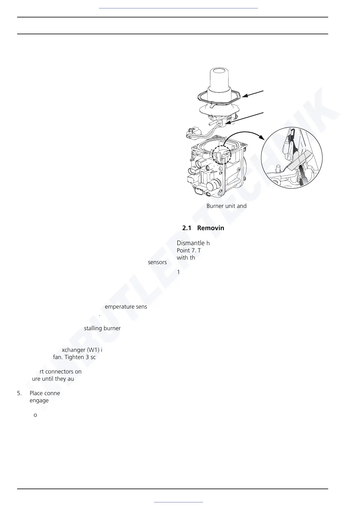
Fig. 902 Burner unit and combustion-air fan unit
9.2.1 Removing burner unit
Dismantle
heater as described in Section 9.1.1 up to
Point 7. The connectors are disconnected. Set down the fan
with the burner unit vertically.
1. Remove the gasket (A7) from the fan housing (G1).
2. Slide grommet (B7) with slight pressure onto fuel pipe
(B5) out of fan housing (G1) while lifting off burner unit
(B) vertically upward.
A7
B7
Visit www.butlertechnik.com for more technical information and downloads.

 Loading...


