5 Troubleshooting Thermo Top Evo
512
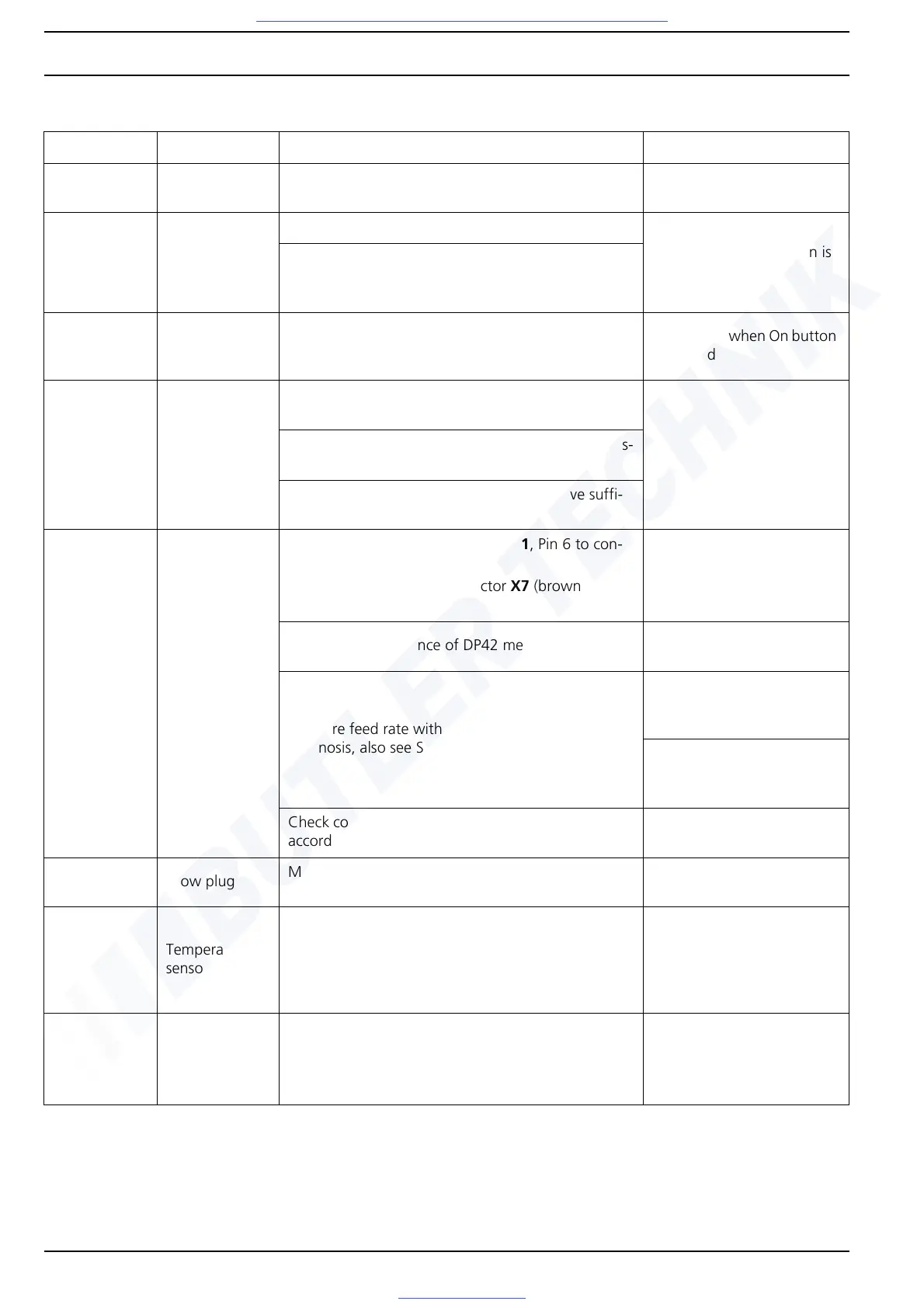
Functional test of heater and its components
Fault Component Recommended workshop action Parameter
1Power supply
Measure supply voltage under load at heater unit
connector X2 (also see Fig. 916)
Undervoltage switch-off
<11.5V
2Clock
Press flame button, display lighting must light up
LED flickers when button is
pressed
Check the W bus signal on Pin 2 on heater unit con-
nector X1 or diagnostic connector with an LED lamp
against "+"
3
Receiver
(Telestart T80
and T91)
Check the W bus signal on the 6-pin connector on
the receiver, Pin 2, with an LED lamp against Pin 1
"+"
LED flickers when On button
is pressed
4
Transmitter
(Telestart)
Assign transmitter to receiver/teach in accordance
with instructions
Check operating mode on Telestart hand-held trans-
mitter (heat/ventilate)
Battery of hand-held transmitter should have suffi-
cient capacity (new)
5 Metering pump
Check continuity from connector X1, Pin 6 to con-
nector X7 (blue wire)
Check continuity from connector X7 (brown wire)
against earth
Measure coil resistance of DP42 metering pump
5.20 ohms ± 0.5 % at
20 ± 2 °C
Measure feed rate with Webasto Thermo Test PC
Diagnosis, also see Section 8.4
Petrol feed rate:
7 Hz, 60 sec: 11.6 to
14.3 ml
Diesel feed rate:
7 Hz, 60 sec: 12.0 to
14.6 ml
Check connection of fuel line on connection piece in
accordance with general installation instructions
6 Glow plug
Measure glow plug resistance on glow plug connec-
tor X5 (white wire), also see Section 9.3.1
At 25 ± 5 °C:
0,235 to 0.355 ohms
7
Temperature
sensors
For information on checking the cold resistance of
the sensors, also see Section 9.6.3
At 20 ± 6 °C:
W5 (Pin 2 and 4)
2,296 to 5,047 ohms
W6 (Pin 1 and 3)
30 to 250 ohms
8
Combustion air
fan
Conduct component test on function of fan motor
with Webasto Thermo Test PC Diagnosis.
No rubbing noises may be heard.
Check CO
2
settings in accordance with Section 8.2
Fig. 504 Overview of functional test of heater and its components

 Loading...


