Thermo Top Evo 9Repair
905
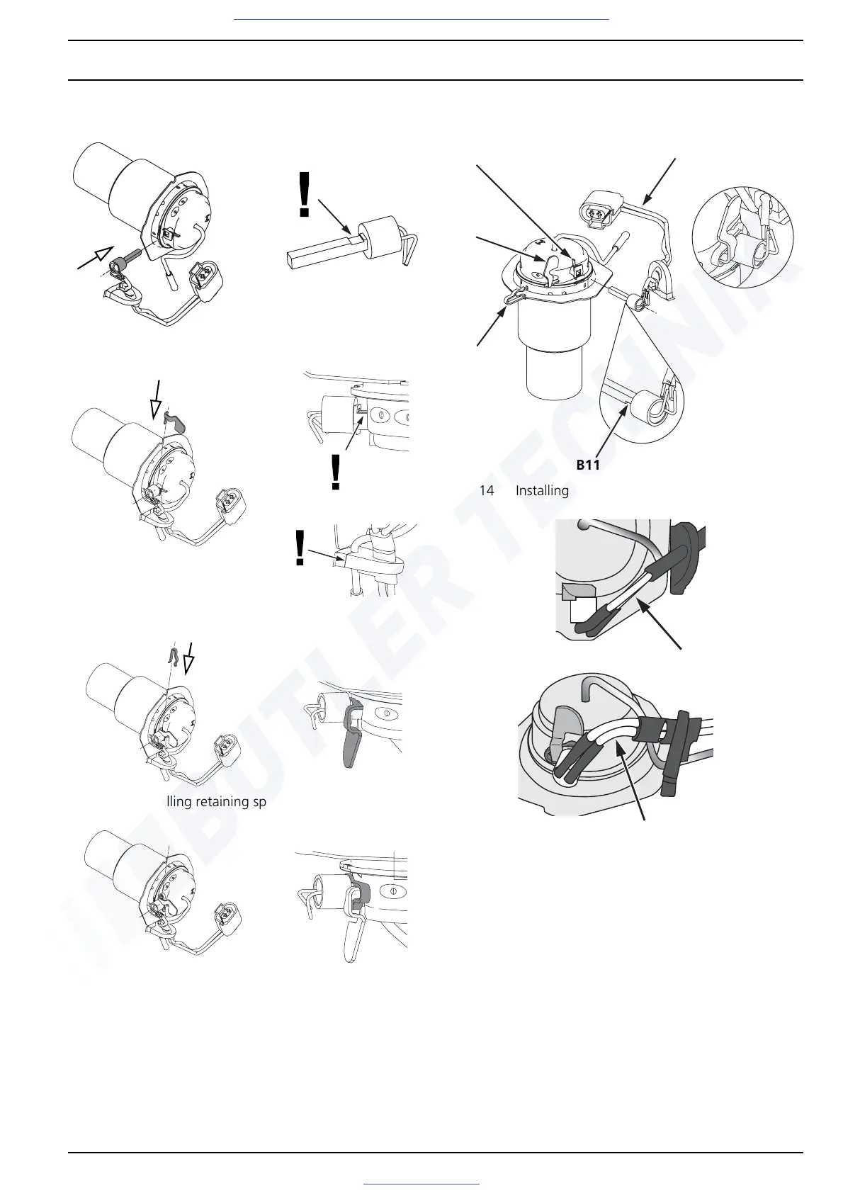
9.3.3 Installing glow plug/flame monitor
Fig. 910 Installing glow plug
Fig. 911 Installing cooling flag
Fig. 912 Installing retaining spring
Fig. 913 Installing glow plug properly
Fig. 914 Installing glow plug
Fig. 915 Routing glow plug cable with slight bend
1. Position combustion pipe with evaporator mount hori-
zontally toward rear (see Fig. 910).
2. Slide glow plug (B4) with unbent cable (B10) as far as
possible into mounting hole of glow plug dome (B8).
IMPORTANT
Install glow plug (B4) with groove (B11, below ceramic)
toward combustion pipe (see detail Fig. 914).
3. Hold cooling flag (B3) in groove (B11) with hand on
glow plug dome (B8) (see Fig. 911 and Fig. 914).
B11
B2
B3
B8
B10
B10
B10
Visit www.butlertechnik.com for more technical information and downloads.

 Loading...


