Thermo Top Evo 9Repair
903
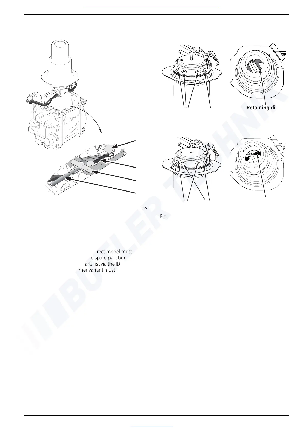
Fig. 903 Detailed illustration of cable routing for glow
plug
9.2.2 Installing burner unit
IMPORTANT
When changing a burner, the correct model must be
ensured! The assignment of the spare part burner must be
carried out using the spare parts list via the ID number of the
burner. The respective burner variant must be checked prior
to installation.
Fig. 904 Petrol burner unit
Fig. 905 Diesel burner unit
1. Pre-position burner unit with grommet (B7) in fan
housing (G1). During installation, make sure that the
glow plug cable (B10) and grommet (B7) are mounted
in the guide and groove provided on the fan housing
(G1) (see Fig. 903). Press grommet (B7) into groove
provided until it completely fill out the installation
space.
2. Mount gasket (A7) on positioning pins of fan housing
(G1) with flat side facing fan housing (G1).
3. Then proceed with the installation of the heat
exchanger (W1) as described in Section 9.1.2.
NOTE
Carry out the "Reset glow plug" routine with the Webasto
Thermo Test PC Diagnosis.
B7
B5
B4
B10
open closed
Retaining disc
open closed
Retaining ring
Visit www.butlertechnik.com for more technical information and downloads.

 Loading...


