9 Repair Thermo Top Evo
906
4. Slide retaining spring of glow plug (B2) over cooling
flag (B3) and glow plug dome (B8) (for orientation of
retaining spring B2, see Fig. 914).
IMPORTANT
The glow plug (B4) must be installed in the glow plug dome
as far as possible.
5. Route glow plug cable (B10) as shown in Fig. 915 with
a slight bend and slide grommet (B7) onto fuel pipe
(B5).
IMPORTANT
Only use a new glow plug during installation. Uninsulated
areas of the glow plug cable must not touch and must not
come into contact with metal parts of the burner unit or the
combustion air housing (danger of short circuits).
The glow plug must not be twisted or jammed and must be
seated in the guide as far as possible during installation
(danger of breakage). When installing the burner unit, the
cable must be routed so that it lies in the groove provided.
Also see Section 9.2.2 and Fig. 903.
NOTE
Carry out the "Reset glow plug" routine with the Webasto
Thermo Test PC Diagnosis.
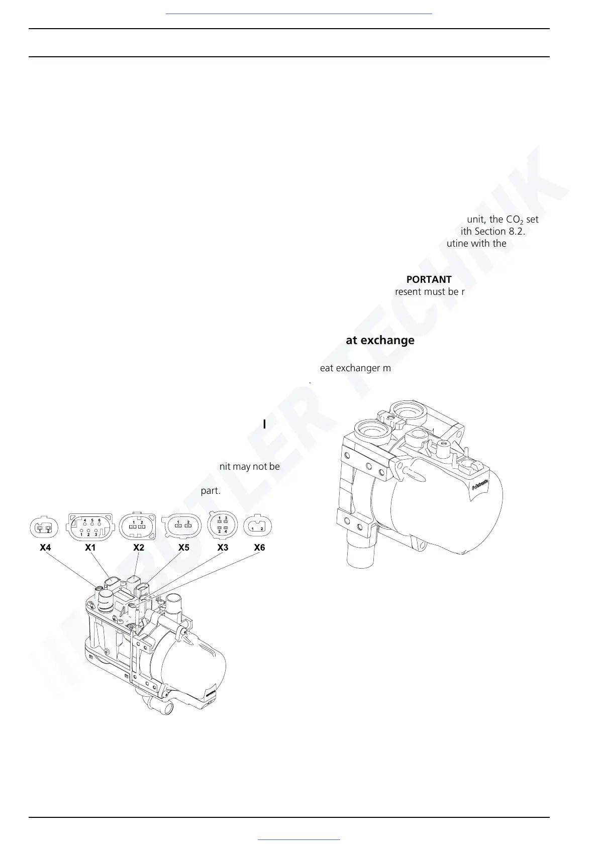
9.4 Combustion-air fan unit and control
unit
The combustion-air fan unit and the control unit may not be
removed.
Combustion-air fan unit assembly spare part.
Fig. 916 Combustion-air fan unit with illustration of con-
nectors
(variant shown is equipped with the maximum
connector assignment)
SG = Control unit with connector baskets
X1 = Heater controller connector
X2 = Connector for power supply to vehicle
Contact 1: Power supply terminal 30
(Fuse)
Contact 2: Earth connection
X3 = Connector for temperature sensors
X4 = Connector for 2x circulating pump
X5 = Glow plug connector
X6 = not in use
NOTE
When replacing the combustion-air fan unit, the CO
2
set-
ting must be checked in accordance with Section 8.2.
Carry out the "Reset glow plug" routine with the Webasto
Thermo Test PC Diagnosis.
IMPORTANT
Any blind connectors present must be remounted on the
new control unit.
9.5 Heat exchanger
The heat exchanger must be replaced as a complete assem-
bly.
Fig. 917 Heat exchanger
IMPORTANT
The heat exchanger may not be dismantled into its individ-
ual parts.
NOTE
Water connection pieces with retaining plate must be
checked for damage and replaced if necessary.
The units temperature sensors, gaskets and screws for water
connection pieces and temperature sensors must be
replaced in accordance with Section 9.6.2 and 9.7.1.
Visit www.butlertechnik.com for more technical information and downloads.

 Loading...


