Thermo Top Evo 8Servicing work
801
8Servicing work
This section describes the servicing work that can be carried
out on the heater and its components while installed.
8.1 Work on the heater
The power supply must always be disconnected at the vehi-
cle battery before carrying out any work on the heater. The
power supply must not be disconnected whilst the heater is
operating or slowing down as a result of the risk of the
heater overheating and the overheating protection thus
being tripped. If repair work is carried out on the heater, it
must be completely removed. After the heater and all cool-
ant-carrying components have been installed, the entire
coolant system must be filled, bled and checked for leaks
with the specified system pressure in accordance with the
vehicle manufacturer's instructions. The general installation
instructions and the vehicle-specific installation instructions
for the heater must be observed when carrying out repairs
which make it necessary to change the installation location.
NOTE
Any coolant running off should be collected using an appro-
priate container.
8.2 CO
2
setting
NOTE
After repairing the heater and/or replacing the metering
pump, the setting of the CO
2
value should be checked.
IMPORTANT
After replacing the fan unit or the control unit, the CO
2
value must be checked and reset if necessary.
The CO
2
setting is carried out with Webasto Thermo Test PC
Diagnosis.
The heater is optimally set to a CO
2
value for operation at
altitudes between 0 and 1,000 m above sea level at the fac-
tory. Continuous operation above 1,000 m above sea level
can lead to heavy smoking and formation of soot.
To prevent a failure of the unit and danger, the CO
2
value
should be adjusted in consultation with Webasto.
NOTE
The CO
2
measurement and setting must be carried out in
the full load heater operating mode (display in Webasto
Thermo Test: Full Load). The CO
2
value is corrected in selec-
tion point 2.7.1. CO
2
calibration of Webasto Thermo Test
PC Diagnosis. The measurement of the CO
2
content is car-
ried out approx. 20 mm in front of the end of the exhaust
outlet inside the exhaust pipe with a CO
2
tester (e.g. from
MSI).
The following table shows the nominal CO
2
setting value in
full-load combustion operation in dependence on the geo-
detic altitude at which the setting is made.
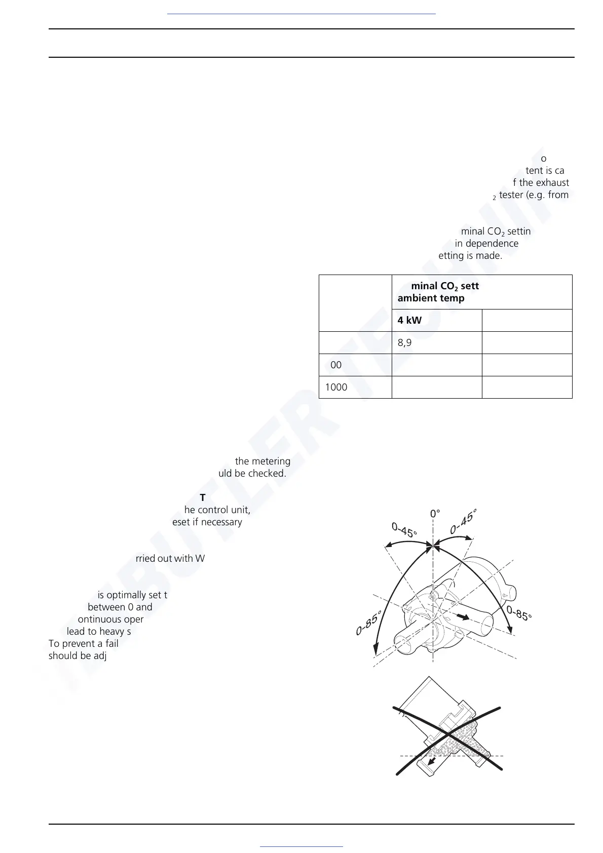
8.3 Circulating pump
The power consumption is approx. 12 W with a nominal
volume flow rate of 450 l/h.
Fig. 802 Installation position of U4847 Econ circulating
pump
Altitude
[m above
sea level]
Nominal CO
2
setting value at 20 °C
ambient temperature [% by vol.]
4kW 5kW
0 8,9 9,5
500 9,5 10,1
1000 10,0 10,7
Fig. 801 CO
2
setting values
Visit www.butlertechnik.com for more technical information and downloads.

 Loading...


