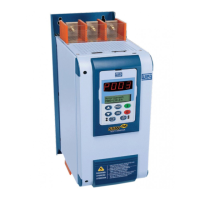
Soft-Starter SSW-06 Characteristics on Fieldbus Network
SSW-06 | 10
is the first or the last element of the network, this switch must be set to Pos. “ON”. If the resistor connector has
been already enabled, the termination switch of the Profibus DP network must be set to OFF.
So you are able to disconnect the network element without impairing the bus, we recommend providing active
terminations that will act as termination elements. In thus way you can disconnect every network drive from the
bus without impairing the termination.
2.1.8 GSD File
Each element of the Profibus DP network is associated to a GSD file that has all information about the element.
This file describes the characteristics of each equipment and is used by the configuration program of the master
of the Profibus DP network. For the Master configuration you must use the configuration file GSD supplied with
the equipment.
HMS Industrial Networks AB has developed the communication board used by the Soft-Starter SSW-06. Thus
in the network configuration software, the product will not be recognized as a Soft-Starter SSW-06 but as
"AnyBus-S PDP" in "General" category.
2.1.9 Profibus DP-V1 – Access to the Parameters
The DP-V1 communication kit supports the DP-V1 services of classes 1 and 2. By using these services, besides
the cyclic data exchange, it is possible to perform services of reading/writing in parameters through DP-V1
acyclic functions, by the network master, as well as by a commissioning tool. The parameter mapping is done
based on the slot and index addressing, as showed in the equationing below:
■ Slot: (parameter number - 1) / 255.
■ Index: (parameter number - 1) MOD
1
255.
The parameter P100, for instance, will be identified through acyclic messages, as being located at slot 0, index
99.
The values for the parameters are always communicated with a size of 2 bytes (1 word). The value is also
transmitted as a whole number, without decimal point, and its representation depends on the used resolution.
E.g.: P003 = 3,6A value read via network = 36.
2.2 DEVICENET NETWORK
The DeviceNet communication protocol has been developed in 1994 by Allen-Bradley and is currently used for
linking controllers and industrial equipments, mainly for sensors, valves, starters, bar code readers, frequency
inverters, operation switchgears and interfaces. There are currently several PLC, processors and communication
device suppliers.
One of the main DeviceNet network characteristics is the use of the CAN - Controller Area Network - for the
message transmission and reception. The CAN bus comprises a twisted pair of wires that transmits a differential
electrical signal responsible for sending a communication signal to all equipments connected to the same
network.
The DeviceNet protocol is an open protocol and you can obtain all information about its technology and so
develop your own communication devices. Currently ODVA (Open DeviceNet Vendor Association -
http://www.odva.org
) is the company that manages the DeviceNet network specification aiming at their
development.
1
MOD represents the remainder of the division.

 Loading...