Soft-Starter SSW-06 Characteristics on Fieldbus Network
SSW-06 | 12
Timeout in the connection to the master
Device is not being supplied/enabled
Data length longer than configured
The LED 3 gives only information about the communication board and in normal status the green LED must be
On continuously. The LED 2 gives information about the connection to the network and informs if the device is
communicating to the masters or not. In normal status, this green LED must be On continuously. Changes on
this LED may be caused due to connection problems with the bus or configuration problems with the network
master.
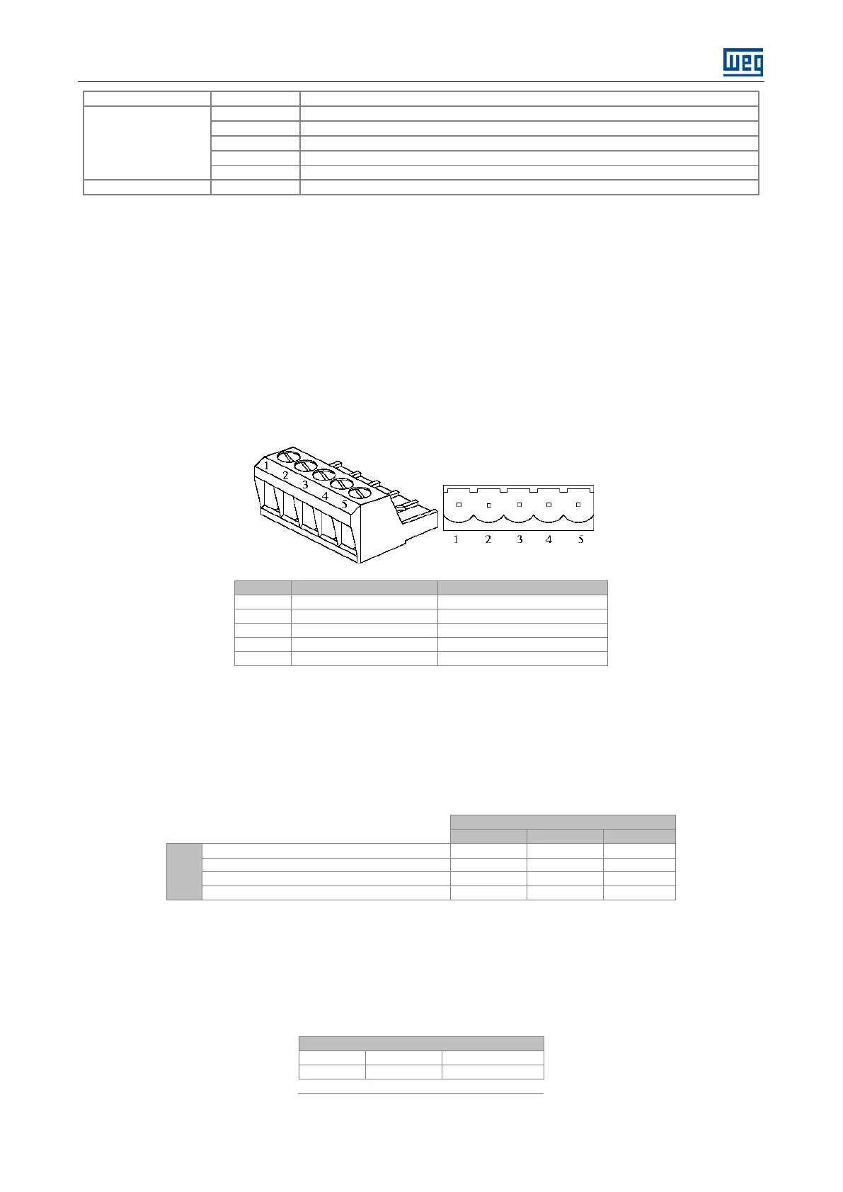
2.2.3 DeviceNet Connector and Network Cable
The Fieldbus kit for the DeviceNet of the Soft-Starter SSW-06 has a female 5 wire plug-in connector that must
be used for the bus connection. The connector pin location, as well as the used standard colors of the
DeviceNet cable, is shown in table below.
Table 8: Connector for the DeviceNet Network
For the connection of the several equipments to the network, we recommend using a shielded cable with two
pairs of twisted wire: one pair for the communication signal transmission (CAN_L and CAN_H) and the other pair
of twisted wire for the supply signal (V- and V+). The maximum allowed cable length depends on the
communication baud rate and on the used cable type. Table below shows the relation between the used
communication rate and the maximum allowed cable length.
Table 9: Maximum length of the DeviceNet cable
Type
Maximum length per cable derivation
Accumulated maximum length of the derivations
2.2.4 Bus Supply
As already informed above, one of the DeviceNet network characteristics is the network cable that must be
formed by one pair of twisted wires to send the voltage supply to all devices connected to the bus. This voltage
is used to supply the interface circuit with the network. Table below shows the current and voltage data of the
power supply for the Soft-Starter SSW-06 communication board.
dc

 Loading...