8
3.3 Installation of air inlet system
Correct design and installation of the air intake system will be one of the key
parameter to achieve optimum engine performance. Opening of air inlet system
should be arranged outside the engine room to ensure fresh air availability to
the engine. Sharp curves and bends should be minimized. Using of sharp bend
(elbows) in the system will create air ow restriction; use large arc bends instead.
The inlet air lter should be provided with an additional protective cover to prevent
ingress of water and dirt into system during rainy season. To take advantage of
air ow during boat movement; opening of the air inlet entry should be preferably
faced towards the front end of the boat.
3.4 Installation of exhaust system
The external exhaust duct should be fabricated with steel pipe. Using of sharp bend
(elbows) in the system will create restriction in exhaust gas outlet; this will develop
excessive back pressure in the system, resulting in poor engine performance. The
complete exhaust ducting should be properly supported and xed to the hull of
the boat. Pay attention to expansion bellow while installing the ducting; ducting
weight should not be exerted on the expansion bellow. After installing the system,
make sure the back pressure is within the limit. Maximum allowable back pressure
in the exhaust system is 6KPa. Exhaust system surface temperature is relatively
high during operation of engine. Avoid installing the exhaust pipe near ammable
objects, so as to prevent any re accidents or injury to the working personnel.
It is advised to provide adequate heat insulation to the external exhaust system
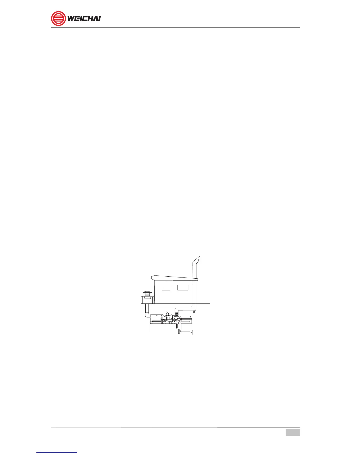
surface. Opening of the exhaust gas outlet should preferably facing rear end of the
boat. The exhaust outlet face should be minimum 1.5 Meters higher than the air
inlet opening. Refer schematic diagram of gure 3.3.
Figure 3.3