10
3.7 Installation of electrical and engine control system
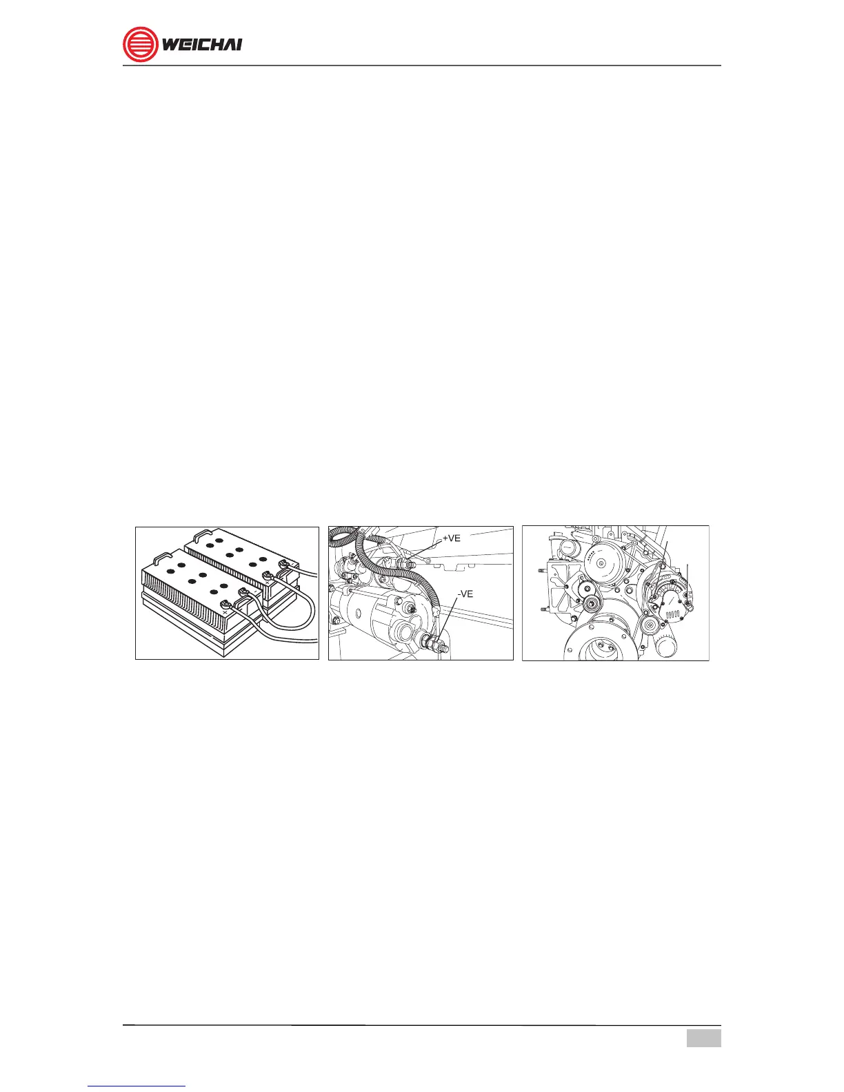
The electrical system is operating on 24V DC supply. Select the battery and
connecting cables according to the engine power range. Identify the positive (+)
and negative (-) terminals of battery, starter motor and charging alternator. Properly
connect the terminals without changing the polarity. Refer gure 3.5, 3.6& 3.7. A set
of engine control panel (main and remote) with necessary wire harness is provided
along with the engine.
The key features of the electrical system are as below:
• Engine control - start and stop control from main and remote panel.
• Important parameter display on main and remote panel.
• Engine Safety – alarm with display and stopping the engine if crossing the safe
operational limits.
Properly mount the main engine control panel on the engine and remote panel in
the wheelhouse dashboard. Connect the wire harness plug in sockets from the
engine to the monitor. Establish the connection between the main and remote
monitors. Conrm all the functions (start, stop, display and safety) are working
properly from main and remote panel.
B -VE
B +VE
Figure 3.5 Figure 3.6 Figure 3.7