iiI.U _
i_iiiiii
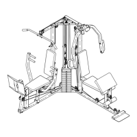
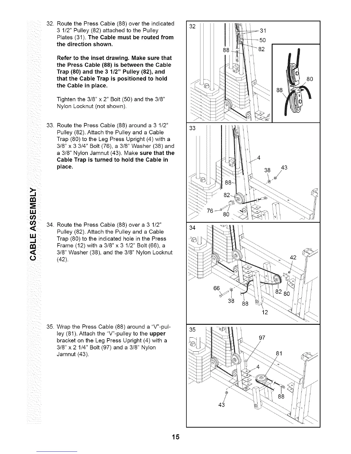
32.
Route the Press Cable (88) over the indicated
3 1/2" Pulley (82) attached to the Pulley
Plates (31). The Cable must be routed from
the direction shown.
Refer to the inset drawing. Make sure that
the Press Cable (88) is between the Cable
Trap (80) and the 3 1/2" Pulley (82), and
that the Cable Trap is positioned to hold
the Cable in place.
Tighten the 3/8" x 2" Bolt (50) and the 3/8"
Nylon Locknut (not shown).
33.
Route the Press Cable (88) around a 3 1/2"
Pulley (82). Attach the Pulley and a Cable
Trap (80) to the Leg Press Upright (4) with a
3/8" x 3 3/4" Bolt (76), a 3/8" Washer (38) and
a 3/8" Nylon Jamnut (43). Make sure that the
Cable Trap is turned to hold the Cable in
place.
34. Route the Press Cable (88) over a 3 1/2"
Pulley (82). Attach the Pulley and a Cable
Trap (80) to the indicated hole in the Press
Frame (12) with a 3/8" x 3 1/2" Bolt (66), a
3/8" Washer (38), and the 3/8" Nylon Locknut
(42).
35. Wrap the Press Cable (88) around a "V"-pul-
ley (81). Attach the "V"-pulley to the upper
bracket on the Leg Press Upright (4) with a
3/8" x 2 1/4" Bolt (97) and a 3/8" Nylon
Jamnut (43).
32
76
43
12
97
38
88\
43
42
81
15