Manual R06-2016 29 / 172
ROTARY INDEXING TABLE CONTROLLER
EF2...B
COMPONENT DESCRIPTIONS | 3.6 Brake Relay
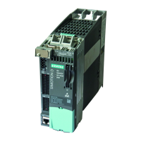
3.6 Brake Relay
A Brake Relay is required for operating motors with holding brakes up to 2 A (included in the scope of delivery).
The Brake Relay is the interface between the CU / Power Modules Blocksize and the 24 V DC motor brake.
The motor brake is electronically controlled.
The supply voltage for the motor brake must be separately connected to the Brake Relay.
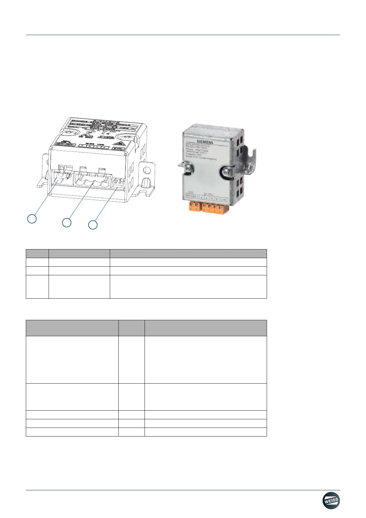
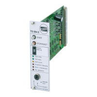
Fig. 12: Interfaces of the Brake Relay
3.6.1 Technical data
Refer to the device manual of the manufacturer for further information.
Pos. Interface Description
(1) - Connection for the solenoid of the motor brake
(2) - Connection for a 24 V DC power supply
(3) -
Connection for the cable harness (CTRL) to the power
module, blocksize format (included in the scope of deli-
very)
Pos. Inter-
face
Description
Power supply
DC 20.4 to 28.8 V
Recommended nominal value of the power
supply 26 V DC (to equalize and compen-
sate for the voltage drop along the length of
the feeder cable to the 24 V DC solenoid of
the motor brake)
Current requirement, max.
Motor brake
at 24 VDC
A
A
2
0.05 + current drawn by the motor brake
Conductor cross-section, max. mm
2
2.5
Dimensions (W x H x D) mm 69 x 63 x 33
Weight kg approx. 0.17