Manual R06-2016 3 / 172
ROTARY INDEXING TABLE CONTROLLER EF2...B
TABLE OF CONTENTS
1 INTRODUCTION ............................................................................................................................................. 7
1.1 Definition ................................................................................................................................................ 7
1.2 Intended use .......................................................................................................................................... 7
1.3 Target group .......................................................................................................................................... 7
1.4 Controller components ........................................................................................................................... 8
1.5 Further applicable documents ............................................................................................................. 11
1.6 Manual ................................................................................................................................................. 11
1.6.1 Validity ................................................................................................................................................. 11
1.6.2 Standard scope .................................................................................................................................... 11
1.6.3 Explanation of safety instructions in this manual ................................................................................. 12
1.6.4 Legend ................................................................................................................................................. 12
1.6.5 Figures ................................................................................................................................................. 12
1.6.6 Directory of valid pages ....................................................................................................................... 12
2 SAFETY ......................................................................................................................................................... 13
2.1 Fundamental safety instructions .......................................................................................................... 13
2.1.1 Operator‘s obligation to exercise diligence .......................................................................................... 13
2.1.2 Technical safety ................................................................................................................................... 14
2.1.3 Electrostatic safety ............................................................................................................................... 15
2.1.4 Ambient and operating conditions ....................................................................................................... 15
2.2 Emergency-off circuit ........................................................................................................................... 15
2.3 Residual hazards ................................................................................................................................. 16
3 COMPONENT DESCRIPTIONS .................................................................................................................... 18
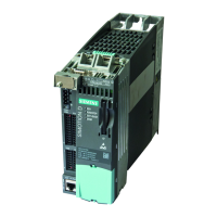
3.1 Power Modules PM240-2 .................................................................................................................... 18
3.1.1 Safety instructions ............................................................................................................................... 18
3.1.2 Power Module PM240-2; frame size FSA ............................................................................................ 19
3.1.3 Power Module PM240-2; frame size FSB ............................................................................................ 20
3.1.4 Technical data ..................................................................................................................................... 21
3.1.5 Overview Power Module PM240-2 ...................................................................................................... 23
3.2 External braking resistor (option) ......................................................................................................... 24
3.2.1 Technical data ..................................................................................................................................... 24
3.3 Motor contactor .................................................................................................................................... 25
3.3.1 Technical data ..................................................................................................................................... 25
3.4 Safety relay .......................................................................................................................................... 26
3.4.1 Technical data ..................................................................................................................................... 27
3.5 Terminal Module TM15 ........................................................................................................................ 28
3.6 Brake Relay ......................................................................................................................................... 29
3.6.1 Technical data ..................................................................................................................................... 29
3.6.2 Brake Relay connection example ........................................................................................................ 30
3.7 SIMOTION D410-2 Control Unit .......................................................................................................... 31
3.7.1 Technical data ..................................................................................................................................... 32
3.7.2 MAC Addresses ................................................................................................................................... 33
3.7.3 CompactFlash Card ............................................................................................................................. 33
4 FUNCTION AND SIGNAL DESCRIPTIONS ................................................................................................. 34
4.1 Signal description of the software inputs ............................................................................................. 34
4.2 Signal description of the software outputs ........................................................................................... 36
4.3 Functions and signals TM15 ................................................................................................................ 38
4.3.1 Terminal Module TM15 connection example ..................................................................................
..... 38